
Q. I am aware that there are requirements for the inlet piping of rotodynamic pumps. What are the requirements for the discharge piping of a pump?
A. The maximum velocity at any point in the outlet (discharge) piping shall be 4.5 meters per second (15 feet per second). This limit will, however, be reduced if there is a check valve in the outlet piping that will generate a hydraulic shock when it closes. Note that the pump discharge nozzle velocity may exceed this value. Therefore, the straight discharge pipe length at the pump discharge nozzle, which will be the same diameter as the discharge nozzle itself, cannot be subject to this velocity limitation.
System pipe friction losses, life cycle costs, and process considerations normally dictate the size of the discharge piping and fittings. If the liquid is a slurry, then the velocity in the discharge pipe may be higher to keep the solids in suspension.
Pipe fittings mounted close to the discharge flange will normally have minimal effect on the performance or reliability of rotodynamic pumps. However, some pumps can be sensitive to flow-disturbing fittings mounted close to the pump discharge. This can result in increased noise, vibration and hydraulic loads. If in doubt, check with the pump manufacturer.
For most pumping systems, an inlet (suction) shut-off valve should be installed in the pump inlet piping for system isolation. Likewise, a discharge shut-off valve should be installed in the pump discharge for system isolation.
The shut-off valve is used during priming, when starting or stopping the pump and during maintenance. Except for axial flow pumps, where the shut-off horsepower is excessive, it is advisable to close the shut-off valve just before stopping and when starting the pump. This is especially important if there is no discharge check valve and the pump is operated against a high static head. In addition, for very high horsepower pumps or pumps with thermally sensitive liquids, it is advisable to throttle the pump to minimum flow
just before starting or stopping the pump.
If a foot valve is not installed in the suction pipe, then a check valve may be necessary between the pump and the shut-off valve to protect the pump from reverse flow and excessive backpressure. If expansion joints are used, they should be placed on the pump side of the check valve to dampen, and not transfer, closure slam. (Do not rely on an expansion joint to dampen the shock of check valve closure. Add a damper to the check valve when shock due to rapid closure of the check valve is likely.)
Submersible turbine well pumps must always have a check valve installed in the discharge line, no more than 7.6 meters (25 feet) (for water at sea level) above the lowest liquid (pumping) level in the well or sump. This distance limit is necessitated by the vapor pressure limitation to ensure that a fluid void will not form under the check valve, which can cause a hydraulic shock or water hammer the next time the pump is started.
At higher elevations, higher temperatures and for liquids with different vapor pressures, this distance must be evaluated and will be less than the specified 7.6 meters (25 feet). The discharge valve and check valve can be replaced by a triple-duty valve that provides both functions in a single body.
Triple-duty valves also provide circuit balance capability and require shorter installed pipe lengths at reduced cost compared to separate valves. Note that triple-duty valves may have a very high energy cost associated with their use. This should be evaluated as part of a life cycle cost (LCC) analysis.
ANSI/HI 9.6.6 Rotodynamic Pumps for Pump Piping is an excellent, must-have resource for pump piping requirements.
Q. Water hammer can be dangerous and cause pipes or fittings to fail. How are the potential pressure peaks to avoid such damage calculated?
A. Yes, water hammer or hydraulic shock is a condition that exists when a column of fluid changes velocity quickly. This condition can exist when the power to the driver is lost suddenly, air is finally expelled from the system piping, a valve is closed too quickly or a check valve closes too slowly and allows backflow to occur before it slams shut.
When this occurs, the kinetic energy is rapidly transformed into pressure energy, which will cause a sharp rise above normal system pressure. This transformation produces an acoustic pressure wave that propagates upstream within the pipe.
When pumps start or stop or the momentum of the fluid in the piping is changed by any other means (such as opening or closing a valve rapidly), a pressure wave is formed. The pressure wave can be either above or below the normal pressure in the piping with the pumps operating depending on the configuration of the piping and pump system.
These pressure waves are called surge pressures or water hammer (when water is the fluid), and their magnitude can be sufficient to burst or collapse piping, valves, machinery casings and other devices.
The magnitude of the pressure wave can be calculated with reasonable precision if the configuration of the piping, the size of the pipes, the materials of the piping, the properties of the fluid and how quickly the pump and/or fluid accelerates or decelerates are all known. When the column of fluid in the piping is either started or stopped, the energy of the system is transformed from velocity energy to head or pressure energy. Because the fluid and piping material are not completely incompressible, they will absorb a fraction of the energy.
This analysis is covered in many hydraulics texts and can be performed with available computer software. This material is provided to inform the designers and users of pump piping systems that a surge analysis is necessary because surge will occur in every pumping system. In most cases, the peak pressure of this surge may be below the pressure that may cause damage, but one cannot determine this solely by any simple rules.
If a valve at the end of the pipe is closed in less than four seconds, the pressure of the surge wave will be maximized. The potential magnitude of the pressure wave can be tremendous. Based on elastic column theory, the formula for the maximum pressure rise for rapid valve closure (prior to the pressure wave making a round trip back to the valve) and no friction loss is as follows:
Metric units
P = ρ x a x V/g
U.S. customary units
P = ρ x a x V/144g
Where:
P = Pressure rise – kPa (psi)
ρ = Liquid specific gravity – kN/m3 (lbf/ft3)
a = Velocity of sound in water – m/s (ft/s)
V = Velocity of the liquid in the pipe – m/s (ft/s)
g = Acceleration due to gravity – 9.81 m/s2 (32.2 ft/s2)
Table B.1 shows the increase in pressure at the crest of the shock wave. This is the increase in pressure over the pressure already in the pump casing. As an example, assume a pump is operating at 345 kPa (50 psi), and the liquid velocity is 1.5 meters per second (5 feet per second). The instantaneous pressure inside the casing will increase to 2503 kPa (368 psi), [or 345 kPa (50 psi) static + 2158 kPa (318 psi)] as indicated in Table B.1 at 1.5 meters per second (5 feet per second).
At a liquid velocity of 2.4 meters per second (8 feet per second), the instantaneous pressure will hit 3797 kPa (558 psi). Pump casings are not usually designed for this magnitude of instantaneous pressure increase.
This equation ignores any dampening effect of the fluid compressibility and the piping material elasticity, so this equation slightly over predicts the maximum surge pressure.
| Velocity | Delta pressure | Velocity | Delta pressure |
| m/s | kPa | ft/s | psi |
| 0.3 | 432 | 1 | 64 |
| 0.6 | 863 | 2 | 127 |
| 0.9 | 1295 | 3 | 191 |
| 1.2 | 1726 | 4 | 254 |
| 1.5 | 2158 | 5 | 318 |
| 1.8 | 2589 | 6 | 381 |
| 2.1 | 3021 | 7 | 445 |
| 2.4 | 3452 | 8 | 508 |
| 2.7 | 3884 | 9 | 572 |
| 3.0 | 4316 | 10 | 635 |
| 3.4 | 4891 | 11 | 699 |
| 3.7 | 5323 | 12 | 762 |
| 4.0 | 5754 | 13 | 826 |
| 4.3 | 6186 | 14 | 889 |
| 4.6 | 6617 | 15 | 953 |
Table B.1 - Magnitude Pressure Waves
Q. Many pump manufacturers show the net positive suction head required (NPSHR) by a pump as a curve that declines in value as it approaches shut off or zero flow. Other manufacturers show this curve with a change in slope which increases in value at about 50 percent of best efficiency point (BEP) flow. Why do some manufacturers do this?
A. The ANSI/HI 1.6 Centrifugal Pump Tests standard defines the NPSHR as the value at which the total head produced by the pump is reduced by 3 percent at a constant rate of flow, as the net positive suction head available (NPSHA) is reduced. One method of determining the NPSHR is accomplished by conducting a series of tests with the rate of flow held constant and the NPSH available to the pump reduced. The result is a family of curves similar to Figure 1.122.
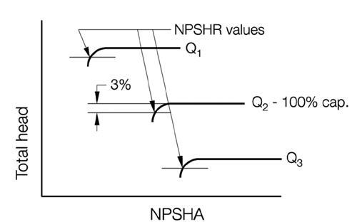 Figure 1.122. NPSH test with rate of flow held constant.
This test will usually produce lower values of NPSHR as the rate of flow is reduced. However, as the rate of flow approaches shut off, the flow at the impeller inlet begins to recirculate in a way that creates vortices between the impeller vanes accompanied by cavitation on the vane surfaces.
This can cause significant damage to the impeller and pump without reducing the pump total head in a measurable amount. Some manufacturers further increase the published NPSHR in this range to avoid such damage to the pump.
Refer to ANSI/HI 1.6 Centrifugal Pump Tests for additional information on pump test curves.
