Editor's Note: This is the fourth article the year-long series, Understanding NPSH. To read the previous article, click here. To read the next article, click here.
NPSHR Shown as a Single Line as a Function of Capacity Only.
Figure 1 is an example of single‑line performance characteristics of a centrifugal pump. The independent variable capacity is plotted on the horizontal scale. Power, head, efficiency and NPSHR are plotted on vertical scales-each as a function of capacity.
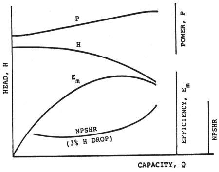
Figure 1. The centrifugal pump family of characteristic curves
Note that the NPSH curve is roughly a lazy "U," reaching a minimum value at a capacity Q about 40 percent of the best‑efficiency capacity. Although most published curves do not show the increased NPSHR at low flows, all centrifugal pumps exhibit such a characteristic. The NPSHR always rises as the pump capacity approaches shut‑off (zero flow rate).
Figure 2 is a typical published performance curve. In this example, the NPSH curve is shown as a single line. (Note that it incorrectly shows the NPSHR to be a minimum at shut‑off.)
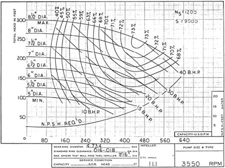
Figure 2. Typical published performance curve. Single-line NPSH curve.
The Effect of Impeller Diameter on NPSHR
Figure 3 shows all parameters in the same fashion except for NPSH. Instead of a single curve that applies to all impeller diameters, lines of "iso‑NPSH" are shown. Note that for the same capacity, smaller diameter impellers require more NPSH.
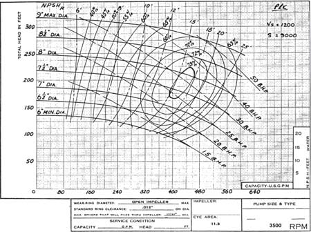
Figure 3. Typical published performance curve. NPSH values increase as impeller diameter decreases.
It is normal to experience a rise in NPSHR as the impeller diameter is reduced since a 3 percent drop of a smaller head (resulting from a smaller diameter impeller) is a smaller head drop. By our definition of NPSHR, we are therefore permitting less cavitation with smaller diameter impellers. Currently there is no known way to predict this increase in NPSHR. Testing must therefore be relied on to establish NPSHR at each impeller diameter.
Is it fair to penalize the smaller diameter impellers? Some pump vendors reason that it is not-the single‑line NPSHR curve, obtained with the maximum‑diameter impeller, should apply to all diameters supplied for that pump.
What if one of those smaller‑diameter impellers is supplied in a smaller‑diameter casing (with a duplicate inlet passage)? We would be required to base our NPSHR on a 3 percent drop of a lower pump head, resulting in a higher NPSHR for the same impeller. Such contradictions account for some of the confusion surrounding this confounding subject of NPSH.
A Method for Eliminating the NPSH Variation Caused by Different Impeller Diameters
Because pump head is a function of the impeller diameter, D2, the traditional 3 percent‑head‑drop NPSH varies as the impeller diameter varies. With the same degree of cavitation in the impeller eye, a pump with a maximum‑diameter impeller will exhibit a smaller percentage of head drop than the same pump with a reduced‑diameter impeller.
Gongwer (3) recognized this shortcoming in our definition of NPSHR. To normalize the NPSH requirements in his tests, he created a "constant" pseudo‑head on which to base his head loss. Rather than use the actual head of the pump, he calculated the head that would be developed with an impeller diameter that was twice the diameter of the impeller eye (D2=2D1). A pump develops a head that is approximately U22/2g. This pseudo‑head is therefore (2U1)2/2g, or 2 U12/g.
The 3 percent head loss therefore converts to 0.03x2UI2/g = 0.06 UI2/g. In U.S. units, this would convert to a head loss, for the 3 percent loss, of ΔH = (DlxN/5300)2. A 5‑in diameter eye, rotating 3,600-rpm, would have an allowable head loss of 11.5-ft (completely independent of impeller diameter and pump head).
Adoption by the pump industry of this revised definition of head loss would be a significant step in normalizing NPSH characteristics. It would be of value to pump users and manufacturers.
Such an adjustment would result in NPSH3 curves being lifted for all pumps with (discharge) specific speeds less than about 1,500, and a lowering of NPSH3 curves for pumps with (discharge) specific speeds above that value.
Prior to the concept of suction specific speed, S, the pump industry attempted to use the Thoma‑Moody concept, sigma, which stated that NPSHR was proportional to pump head. It is not. Numerous authors have so confirmed. S enabled us to begin decoupling NPSHR from H. Adoption of the above suggested criterion would be a further step in decoupling these two independent characteristics.
Prior to the development of the NPSH concept, a performance curve would sometimes show the inlet characteristics of a centrifugal pump as lines of constant "maximum suction lift," as can be seen in Figure 4.
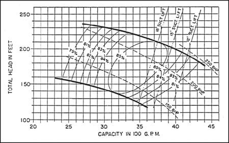
Figure 4. An older performance curve that shows maximum suction lift instead of NPSHR (Acknowledgement is made to the Center for Professional Advancement, Applied Pump Technology Course)
Actual NPSH Test of a Centrifugal Pump
NPSHR is a difficult characteristic to measure, and to further complicate matters, pump manufacturers often disagree on the appropriate testing method and acceptance criterion. The most widely‑accepted criterion is the 3 percent head drop, as specified by API 610 (1). (There is also disagreement on the definition of "non‑cavitating head.") Figure 5 shows the test results obtained during an NPSH test on a centrifugal pump.
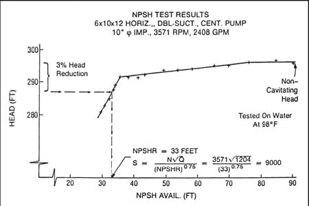
Figure 5. Actual NPSH test points for a process centrifugal pump
To get an NPSH point, we held the capacity constant while reducing the NPSHA. For each point, we plotted head as a function of NPSHA. We then determined how much NPSH was available when the head dropped 3 percent, which was the NPSHR for that capacity.
To obtain a single point for the NPSHR curve, it is necessary to run a pump at a fixed capacity for an extended period of time. Because of the problems of running a centrifugal pump near shut‑off for any extended period (heating, radial thrust, recirculation, pulsations and vibrations), we avoid trying to get NPSHR values at low capacities.
When we plotted our points and smoothed a curve through them, we got a curve as shown in Figure 1.
We heard a loud crackling sound coming from the pump as we reduced the NPSHA. That destructive sound helped us to understand how cavitation could damage pump components. We also noted that the sound level reached a peak, then dropped as we approached the 3 percent point.
So here is the question: If you bought this pump, installed it in your plant, and provided the "required" 33-ft of NPSH, would the pump be cavitating?
The answer is yes!
If pumping cool water, it would cavitate enough to cause the head to be down by 3 percent, which is a lot of cavitation.
How much NPSH is required to eliminate all cavitation? If you provided 75-ft, would that stop the cavitation? That would get the head back up to "non‑cavitating head," but, unfortunately, even at that point, there is still a significant amount of cavitation in the impeller eye. But how much more NPSH is required to eliminate all cavitation?
To address this question, the Hydraulic Institute formed the NPSHA Margin Work Group. Initial conclusions of this group were published in the August 1997 issue of Plant Services Magazine (2). Key points in the article include the following:
-
Cavitation exists in all centrifugal pumps.
-
NPSHA at incipient cavitation can be from 2 to 20 times the "3 percent" NPSHR.
-
Achieving full (100 percent) head requires from 1.05 to 2.5 times the "3 percent" NPSHR. (In Figure 5, we can see that this ratio is about 2.3.)
A study by this author revealed that the NPSH required to achieve incipient cavitation for the typical pump at a capacity correspondent with no prerotation at the impeller inlet is a function of the impeller inlet vane angle, and varies from 2 to 10 times the NPSH3.
We can conclude that it is normally not practical to try to eliminate cavitation, but what is a reasonable margin that we should strive for in our system designs? (We will try to answer that in future articles.)
References
-
Centrifugal Pumps for General Refinery Service, API Standard 610, American Petroleum Institute, 1220 L Street NW, Washington, DC 20005
-
"Cavitation Problems?", Hydraulic Institute NPSHA Margin Work Group, Plant Services, August 1997
-
Gongwer, Calvin A., NA "Theory of Cavitating Flow in Centrifugal‑Pump Impellers", ASME Hydraulic Div. Semi‑Annual Meeting, Milwaukee, WI, June 1940