
Plastic pneumatic diaphragm pumps are used widely in chemical, semiconductor and pharmaceutical applications, as well as other industries that require sanitary operating atmospheres. These pumps are ideal for these applications because of their almost universal chemical resistance-due to housing materials constructed of PTFE (polytetrafluoroethylene) and conductive PTFE-and high wear resistance-thanks to housing materials that use PE (polyethylene) and conductive PE. With the increasing degree of automation found in plant construction and operation, functional reliability is playing an enhanced role with respect to a plant's total cost. Therefore, it is crucial that the right components contribute to a plant's operation (for example, comparatively low-cost pumps that are small, but effective) as unscheduled plant shutdowns and production downtime quickly result in high costs.
The Challenge
Finding the proper pump for a specific production process requires a lot of legwork. Different pump modes of operation must be considered-from positive displacement to centrifugal to peristaltic-along with workload, flow rates, working pressures, etc. One style of pump for chemical, pharmaceutical or semiconductor operations is pneumatic diaphragm pumps. These pumps are commonly used in static-fluid energy machines characterized by energy conversion in an enclosed working space with periodic energy transfer. Appropriate to their mode of operation, these pumps are classified as lift-displacement machines. Features of pneumatic diaphragm pumps are a gentle product displacement, dry-running and overload-proof operation, self-priming, insensitivity to solids, infinite variability and easy-to-operate functions. One key to pump efficiency is its ability to provide a uniform delivery flow. To achieve this uniform flow rate, along with design-related, low-residual pulsation, pneumatic diaphragm pumps are usually designed as externally circulated double-diaphragm pumps (Figure 1). Two identical diaphragms are arranged opposite of each other, with each separating the air chamber from the product chamber, while they are interconnected by means of a piston rod.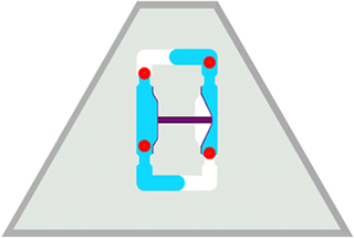 Figure 1
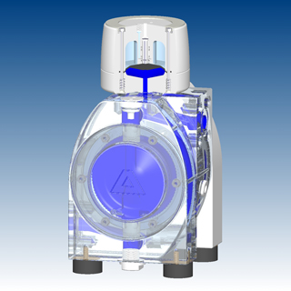 Figure 2
The Solution
Air-control systems operate under extreme conditions. They switch up to 10 cycles per second, are subject to pressure differences up to 7 bar, come into contact with chemically aggressive atmospheres depending on the pump application, and must be reliable and maintenance-free for the above reasons. These requirements are met only by precision controls, such as pneumatically piloted air-control systems. To achieve high-reversing frequencies, a pneumatically piloted air-control system makes use of two compressed air properties, high flow rates and small mass. The pneumatically piloted air-control system has only two moving components (the main and pilot pistons), is a 5/2 way valve (Figure 3) and consists of four different, completely metal-free components (Figure 4). The pilot piston controlled by the diaphragm opens and closes via control edges. Air passages below the main piston alternately apply compressed air to the left or right side downstream of the main piston. This pneumatically switches in a horizontal direction, alternately supplying the diaphragms with compressed air or discharging the expanded air.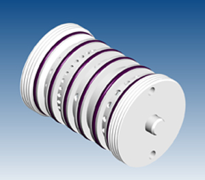 Figure 3
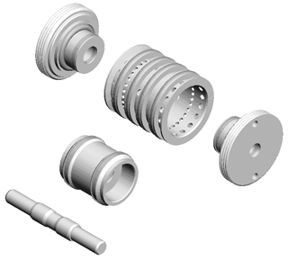 Figure 4
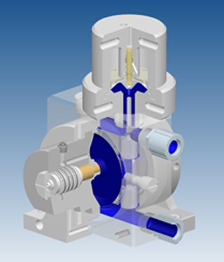 Figure 5