Automatic optimization for pump design is a primary focus for many companies. Efficiency levels for several turbomachinery applications have been maturing in recent years. The introduction of computational fluid dynamics (CFD) in the design process led to some significant improvement in performance, but further improvements are increasingly more difficult to achieve. The conventional design process, which is based on iterative changes to geometry, relies on the previous experience of designers and tends to encourage designers to stay within their comfort zone. This can limit the design space and make it more difficult to achieve significant breakthroughs or meet the demanding multi-objective, multi-point, multi-disciplinary requirements of modern turbomachinery.
What are the challenges addressed by automatic optimization?
Design objectives in turbomachinery are contrasting in many ways. Consider aerodynamic efficiency and structural integrity. A thinner blade can be more efficient, but at the expense of poorer structural performances. In principle, all turbomachinery applications share common challenges, whether one looks at multidisciplinary problems—such as aerodynamic with mechanical performance, noise and efficiency in fans and compressors—or good suction performance subject to minimum shut-off head and high efficiency at different operating points in pumps.
 Parameterized blade loading, or pressure jump across the blade, four to eight loading parameters are equivalent to 30 to 100 geometrical parameters.
Robust design optimization must also be considered with the goal of making the design performances less dependent on operating changes. Automatic optimization can help find solutions to all the described design challenges, yet it is rarely used in the daily design process.
What are the main barriers to the adoption of automatic optimization?
Many current examples of automatic optimization are executed as research projects in universities. They rarely make their way into the industrial design process in which development time and resources are the main barriers. Optimization is commonly used in 1-D design and in some cases 2-D (through-flow) design. However, the application of 3-D optimization of blade geometry has proven more difficult.
 Thousands of designs can be evaluated in just a couple hours, with only the most promising to be evaluated in 3-D CFD.
One challenge is the integration of all the steps into an automated process—from 3-D geometry generation, to meshing for CFD and finite element analysis (FEA) calculations, and finally feeding back the CFD/FEA results to the optimizer. Streamlining this process can save considerable time and reduce the number of user interventions.
Some currently available commercial tools can help achieve a seamless optimization process. However, the key to using automatic optimization daily is 3-D geometry parameterization. Geometry parameterization can be a limiting factor when using optimization in industrial conditions, because between 30 and 100 design parameters are typically needed to represent 3-D blade geometry accurately. This has a direct influence on the type of optimization workflow that is available and the number of designs required to achieve valid results. Ultimately, it defines the product development time.
What different types of automatic optimization workflows exist for turbomachinery design?
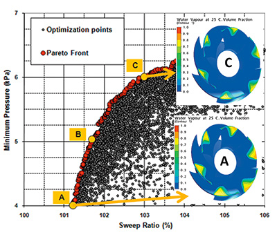
To use optimization in design, the design space must be explored as widely as possible. Gradient type methods are faster computationally but tend to find local minima. The goal is to use evolutionary approaches such as genetic algorithm (GA), which can explore the design space widely and find global minima of objective functions. GAs can also cope better with multi-objective criteria and create Pareo-optimal fronts that show trade-offs between different design parameters.
Having trade-off information can be useful for designers and can help them provide customized solutions. However, GA generally requires a large number of objective function evaluations, typically running into the thousands. Since many problems are multi-point, this makes the application of GA coupled with full CFD or FEA computationally expensive.
Another alternative is to use some form of surrogate model. In this approach, a design matrix is generated by using design of experiments (DoE), which is then used to create a surrogate model through a quadratic regression (response surface model) or other methods, such as artificial neural network or kriging. These surrogate models can then be validated. If accurate enough, GA can then be run on them, which can save considerable computational time because each CFD or FEA evaluation becomes a polynomial evaluation. However, in general, accurate surrogate models can only be obtained when the number of design parameters is a handful. Larger numbers of design parameters generally result in higher errors in the surrogate model. Are 3-D geometry parameterization and the number of input design parameters the keys to making automatic optimization part of commercial product development? They are, absolutely. One piece of geometry parameterized by just 30 parameters requires close to 1,000 designs to be evaluated just for the initial DoE database. Even with high computational capabilities, this is not something that allows a design to be developed in a few weeks by most companies. In contrast, parameterization of the same geometry via 3-D inverse design methods can be completed with six to 10 parameters. This means that only 40 to 100 designs are needed, basically reducing the number of computations by factors of 10 to 20.
How is the blade geometry parameterized via 3-D inverse design?
Different approaches are used for parameterization of blade geometry. In axial machines, the use of some form of surface definition is customary, while in many radial and mixed flow applications, the blade angle is generally used to control the camber distribution. Several control points are used between the leading edge and the trailing edge on 2-D sections that are then stacked together to form a 3-D geometry.
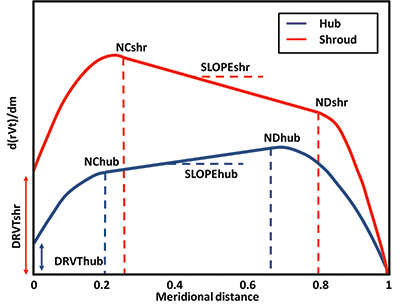
In 3-D inverse design, the blade loading or pressure jump across the blade is parameterized. The implementation is such that, with four to eight parameters of blade loading, designers can cover as much design space as is covered with more than 30 parameters when using blade angles. This reduction in design parameters makes the application of a surrogate model a practical reality for 3-D design.
Are there additional benefits to using 3-D inverse design?
Yes, the first instance is in blade loading. It is common to all turbomachinery applications, and this allows for easy parameterizing of any type blade for all turbomachinery applications and all components—such as axial, mixed-flow or pumps and centrifugal fans, compressors, turbines and torque converters. This eliminates the need for different geometry parameterization systems.
Another difficulty in optimization is choosing the correct range of variation of design parameters. Ideally, the parameters should be varied as widely as possible to cover a large part of the design space but at the same time avoid unrealistic designs. By looking at blade loading, it is easy to see the correct range because unrealistic cases—such as negative loading in compressors—can be seen, and the appropriate level can be chosen accordingly.
Another major benefit is that the optimum blade loading for a given flow phenomena seems to have generality and is independent of flow rate or the diameter of the machine.
What are some applications of 3-D inverse design and automatic optimization?
Many publications and customer testimonials highlight the benefits of 3-D inverse design for turbomachinery design optimization. In the pump industry, both Carver Pumps in the U.S. and Ebara Corporation in Japan have successfully applied this method to the development of new pump series. Also, McQuay in the U.S. recently presented application of coupled 3-D inverse design with DoE for the optimization of a centrifugal compressor stage for the refrigeration industry. P&S