
Q. Some slurry applications include froth in the liquid, which affects pump performance. What must be done when selecting centrifugal pumps for such applications?
A. Froth is an aerated liquid medium (slurry) that occurs naturally or is created on purpose. Natural occurrence may be due to the nature of the ore processed in the mineral industries, creating a general nuisance in many cases.
Froth is created for the purpose of separating minerals, floating the product from the waste or vice versa. It is created by the aeration of the slurry through air injection during agitation with the addition of polymers to increase the surface tension. This creates bubbles to which the product or waste adheres, which allows for the separation and collection of the sought-after mineral for further refining.
The transfer of froths with centrifugal slurry pumps is a special purpose application commonly encountered in the launders of flotation circuits. The very large proportion of air in the froth being handled upsets the normal relationships that are used to predict pumping performance and requires a unique approach when selecting and applying pumps for this service.
Depending on the process, type of slurry or frothing agents used, a certain amount of air or gas will separate from the froth and can lead to problems with pump performance. The change in performance because of this air or gas could be quantified based on various factors, such as pump geometry, specific speed and suction pressure.
However, determining with reasonable accuracy what amount of free air or gas will separate from the froth at the impeller inlet is practically impossible. This problem requires the selection of a pump that can successfully handle the froth application.
The usual approach is to oversize the pump for the application by using a "froth factor." The froth factor is a multiplier that increases the process design capacity to allow for the increased passing volume caused by the gas in the froth.
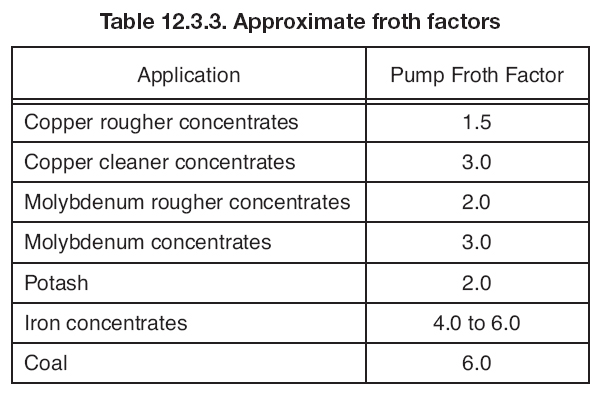
The froth factor is normally specified by the pump buyer and is based on previous plant experience. The factors are usually in the range of 1.5 to 4 but can be as high as 8. Many factors influence the size of the froth factor. These may include the viscosity of the liquid, the size of grind of the mineral and the chemistry used in the process. The type of pump selected will also have an effect on the froth factor used, and the pump manufacturer should be consulted for sizing recommendations. Some typical vertical pump froth factors for common processes are given in Table 12.3.3. These are only approximate values. The most reliable factors will come from the end users.
ANSI/HI 12.1-12.6 Rotodynamic (Centrifugal) Slurry Pumps, Section 12.3.3 includes additional information on froth pumping which will answer more questions. A new revision of this standard is expected to be released this summer.
Q. Is there a standard procedure for measuring airborne sound emitted from industrial pumps?
A. Yes. ANSI/HI 9.1-9.5 General Guidelines for Pumps includes Section 9.4: Measurement of Airborne Sound. The purpose of this standard is to provide uniform test procedures for the measurement of airborne sound from pumping equipment.
This standard applies to centrifugal, rotary and reciprocating pumping equipment. It specifies acceptable and expedient operating conditions and procedures for use by non-specialists, as well as acoustic engineers.
This standard does not apply to vertical submerged wet pit pumps. In this standard, a sound pressure level of 20 µPa (0.0002 µbar) is used as reference. Subsections in this standard include the following:
9.4.1 Instrumentation
Describes the instruments to be used
9.4.2 Operation of pumping equipment
Whenever possible, sound tests shall be made with the pump operating at rated application conditions.
9.4.3 Test environment
It is desirable to conduct tests in a free field above a reflecting plane and not influenced by reflections from walls and nearby objects. A 6 dB drop-off in sound pressure level in each octave band of interest in all directions around the machine, regardless of distance, indicates approximate free-field conditions and gives sufficient accuracy for the purposes of this test standard.
9.4.4 Microphone locations
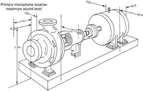
A preliminary survey shall be taken around the machine at a distance of 1 meter (3 feet) from the nearest major surface of the machine and at a height of 1.5 meters (5 feet) to locate the point of maximum overall sound level (A-weighted). This is the primary microphone location. (For a visual example, see Figure 9.4.)
9.4.5 Measurement technique
The period of time during which the measurements are made shall be long enough to allow an average reading to be taken with the slow response setting of the meter.
9.4.6 Measurements to be taken
The following measurements are to be taken at each of the microphone locations, with the machine operating under the conditions stated in Section 9.4.2:
– Overall sound level using the "A" weighing network
– Octave band sound pressure levels using the flat response network
9.4.7 Calculation and interpretation of readings
Whenever there is less than a 10 dB difference between the machinery operating and background sound levels, corrections should be applied.
9.4.8 Presentation of data
Content of report including tables and graphs
Q. Radial thrust on impellers in volute casings increases as the rate of flow decreases. Is this also the case in vertical turbine pumps?
A. Radial thrust is a lateral force, in a direction perpendicular to the shaft, acting against the rotor. Radial thrust generated in a vertically suspended vertical turbine pump (VTP) bowl assembly is considered very low. Pressure forces around the impeller periphery are equalized by the multivane bowl diffusers. In theory, this eliminates pump rotor loading on the sleeve-type bowl bearing bushings. Therefore, the multivane diffusers provide a broad flow range of hydraulic stability. This is generally true for specific speed pumps less than 120 (6,000) ns with a continually rising head-capacity curve.
Radial rotor thrust forces can develop later in a bowl assembly life. In general, these forces occur from impeller hydraulic and mechanical imbalances due to loss of material from erosion, corrosion, cavitation, mechanical problems, etc.
Ideally, a vertical pump's rotor assembly is suspended, hanging plumb from the thrust bearing, and in this condition, the lower portions of the rotor do not rest on the sleeve bearing bushings. When the pump mounting is tilted from plumb vertical, gravity will pull the rotor (shafting) to rest against the sleeve bearing bushings.
As a result, additional sleeve bearing bushing wear may occur from a portion of the rotor weight acting laterally against the sleeve bearing bushings, especially during frequent operational cycles of start-up and shut-down or when the pumped liquid contains abrasive solids. However, inclined vertical pumps are occasionally the best solution for an application, given the appropriate selection of bearing and lubrication options.
Pumps & Systems, August 2011
Pump FAQs® is produced by the Hydraulic Institute as a service to pump users, contractors, distributors, reps and OEMs as a means of ensuring a healthy dialogue on subjects of common technical concern.
HI standards are adopted in the public interest and are designed to help eliminate misunderstandings between the manufacturer, the purchaser and/or the user and to assist the purchaser in selecting and obtaining the proper product for a particular need.
As an ANSI approved standards developing organization, the Hydraulic Institute, process of developing new standards or updating current standards requires balanced input from all members of the pump community.
