
Q. What is the preferred method for starting reciprocating power pumps?
A. Starting a reciprocating pump with a closed discharge valve is naturally difficult due to the high torque required to overcome discharge pressure as well as accelerate the pump. For this reason, reciprocating pumps are typically started with an open bypass line from the discharge to the suction.
To accomplish this, the operator manually opens a bypass valve, or a power-actuated dump valve is programmed to open automatically, which bypasses the liquid during the start and stop functions.
A check valve is employed in the pump discharge line. It remains shut as long as the bypass (dump) valve remains fully or partly open (see Figure 6.47).
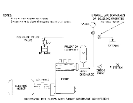
Figure 6.47. Schematic of liquid bypass system
The liquid pressure exerted on the plungers (or pistons) is largely caused by liquid mass and friction as it passes through the bypass valve and piping.
When correctly sized, the bypass valve and piping cause low back-pressure. Only a relatively small torque is required while bypassing the liquid to a tank.
With liquid bypass, the total starting torque requirement is mainly related to the mechanical inertia of the pump, couplings, gears and motor rotor. These components are heavy, and substantial starting torque may be required. All the liquid in the pump suction line and bypass line must be accelerated from standstill to full liquid velocities.
The torque needed to accelerate the entire mechanical hydraulic inertia system depends on the inertia of all the moving parts, including the liquid, the rate of acceleration and the total system friction.
Some pumps are provided with mechanical suction valve unloader devices. These devices reduce the total starting torque requirement to that needed to accelerate the mechanical items, such as pump crankshaft, gears, couplings, etc. They stop liquid pumping action by mechanically holding open the pump's suction valves, allowing the liquid inducted into each liquid cylinder to be delivered back into the pump suction.
Because no liquid pumping occurs, the driving machinery does not need to provide any torque to accelerate the liquid. Only the torque to overcome mechanical inertia and friction is needed during start-up. After the pump and driver have reached full speed, the suction valve unloading devices are retracted, and normal pumping action then commences. At this point, the driver must supply additional torque to accelerate the liquid system and also meet the total running torque requirement caused by discharge pressure.
More information on reciprocating pumps can be found in ANSI/HI 6.1-6.5 Reciprocating Power Pumps for Nomenclature, Definitions, Application and Operation.
Q. What is critical speed when referred to a pump?
A. Critical speed is one or more speed values that coincide with a natural frequency of vibration of the pump rotor or structure. A resonant condition can result when the operating speed or vane-pass frequency of the pump excites the structure's natural frequency. At resonance, the vibration levels will be amplified depending on the amount of damping present in the system.
Much attention is often given to the value of the natural frequency of the pump assembly; however, in a field installation, the structure comprises-in addition to the pump-the foundation, the mounting, the piping and its supports, and may include the driver and coupling or driveshaft(s), as applicable. The natural frequency of the total structure may therefore differ significantly from the natural frequency of the pump alone.
The system designer should consider this to ensure an appropriate separation margin exists between the system's natural frequency and the operating speed. For systems that operate over a speed range, natural frequencies may fall within the operating range and critical speeds may be identified. In such cases, due care and consideration must be taken to evaluate the possibilities of avoiding such operating speeds or mitigating the possible effects on bearing housing (or other) structural resonances.
See HI Standard ANSI/HI 9.6.4 Rotodynamic Pumps for Vibration Measurements and Allowable Values for more details.
Q. Why are some rotary pumps built with timing gears and others are not?
A. Timing gears are intended to synchronize the rotation of two separate rotors in pumps that use screws, gears, lobes or similar devices to move liquid through the pump. See Figure 3.16. The timing gears can be seen on the right hand end of the rotors.
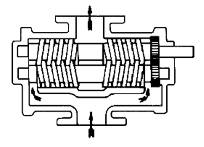
Figure 3.16. Two screw pump
Some rotary pumps, such as sliding vane pumps, have a single rotor, and synchronizing two rotors is meaningless. Some two rotor pumps such as gear pumps rely on the driven rotor to drive the second rotor, and timing gears are not used. However, when pumping abrasive liquids the addition of timing gears will relieve the pressure between the meshing gear teeth in the pump and reduce wear. In this case the timing gears are moved out of the pumping chamber and sealed against leakage along the rotor shaft.
Lobe pumps and some screw pumps cannot drive the second rotor from the first rotor and timing gears are then necessary.
More detail on rotary pumps can be found in ANSI/HI 3.1-3.5 Rotary Pumps for Nomenclature, Definitions, Application and Operation.
Pumps & Systems, August 2010
