
Pumps & Systems, April 2007
Rotary screw pumps have existed for many years and are manufactured around the world. More demanding service requirements impose challenges on screw pump manufacturers to provide higher pressure or flow capability, better wear resistance, improved corrosion resistance, improved efficiencies and lower leakage emissions. Better materials and more precise machining techniques, as well as engineering innovation, have led to improvements in all these areas.
The first screw pump built was probably of an Archimedes design used to lift large volumes of water small vertical distances. They are still manufactured and used for this service. Modern three screw high performance pump deliver liquids to pressures above 4500-psi (310 bar) and flows to 3300-gpm (750-m3/h) with long term reliability and excellent efficiency.
Twin screw pumps achieve flow rates to 18,000-gpm (4000-m3/h), pressures to 1450-psi (100 Bar) and can handle corrosive materials, again at good efficiencies.
Multiple screw pumps provide remarkably good operating efficiencies versus centrifugal pumps when handling viscous liquids such as heavy crude oil, bunker or residual fuel oils and low sulfur fuels. The high efficiency performance is a clear advantage over centrifugal pumps where liquid viscosity exceeds 100 SSU (20 centistokes). See Figure 1.
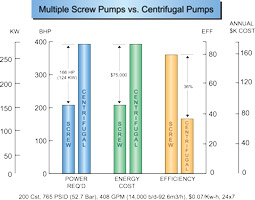 Figure 1. Multiple Screw Pump Efficiency
Not only are annual power savings substantial, but the initial driver, starter and cabling costs are also lower for multiple screw pumps. Operating liquid temperatures as high as 600-deg F (315-deg C) have been achieved in twin screw pumps for the ROSE® deasphalting process (see Figure 2).
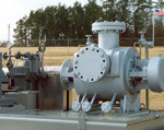 Figure 2. A ROSE® process 600-deg F twin screw pump.
Timing gears and bearings are force cooled while the pump body is jacketed for a hot oil circulating system to bring the pump to process temperature in a gradual, controlled manner. Three screw pumps have been applied to the same elevated temperature, more commonly on asphalt or vacuum tower bottoms services in refineries.
To quote Dushyant Mehra, research analyst with Frost & Sullivan, "The primary challenge for oil & gas pump manufacturers is to improve the energy costs and efficiency of their pumps." 1 The pump user can also contribute to their bottom line by using the most efficient technology to move liquid products. Many times this is a positive displacement pump, not a centrifugal pump. Figure 2A shows excellent efficiency over a broad range of discharge pressures.
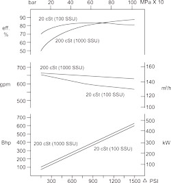 Figure 2A. A typical multiple screw pump performance curve.
In multiple screw pumps, each wrap of screw thread effectively forms a stage of pressure capability. High pressure pumps have 5 to 12 stages, or wraps, whereas low pressure pumps may have only 2 or 3 wraps. This staged pressure capability is illustrated in Figure 3. More wraps are incorporated into pumps designed for higher pressure service.
Three Screw Pumps: Principle Applications
Three screw pumps are the largest class of multiple screw pumps in service today. Typical applications include machinery lubrication, hydraulic elevators, fuel oil transport, fuel oil burner service, power hydraulics and refinery processes, such as high temperature viscous products including asphalt, vacuum tower bottoms and residual fuel oils.
Three screw pumps also find extensive use in crude oil pipeline service, as well as gathering, boosting and loading of barges and ships. These pumps are also used for high pressure distillate fuel injection for gas turbines.
Designs are now available in sealless configurations, such as magnetic drives and canned arrangements, to allow customers to reduce emissions and meet government guidelines. Three screw pumps are renowned for their low noise levels, high reliability, ease of repair and long life.
Design and Operation
Three screw pumps are manufactured in two basic styles, single suction and double suction (see Figure 4). The single suction design is used for low to medium flow rates and low to very high pressure. The double suction design is really two pumps in parallel in one casing, used for medium to high flow rates at low to medium pressure.
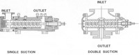 Figure 4. Single and double suction three screw pumps.
Three screw pumps generally have only one mechanical shaft seal and one, or perhaps two, bearings that locate the shaft axially. Internal hydraulic balance is such that axial and radial hydraulic forces are opposed and cancel each other. Thus, bearing loads are very low.
Another common characteristic of three screw pumps is that all but the smallest, low pressure designs incorporate replaceable liners in which the pumping screws rotate. Minor repair kits (seals, gaskets, bearing) and major repair kits (all wearing parts, including those in the minor repair kit) allow easy field repair of most three screw pumps. So field repair is a simple matter and the piping does not have to be disturbed.
The center screw, called the power rotor, performs all the pumping. The meshed outside screws, called idler rotors, cause each liquid-holding chamber to be separated from the adjacent one, except for running clearances. This effectively allows staging of the pump pressure rise. Because the center screw is performing all the pumping work, the drive torque transferred to the idler rotors is only necessary to overcome viscous drag of the cylindrical rotor spinning within its liner clearance.
The theoretical flow rate of these pumps is a function of speed, screw set diameter and the lead angle of the threads. Basically, flow rate is a function of the cube of the center screw diameter. Slip flow is the volumetric inefficiency due to clearances, differential pressure and viscosity. It is a function of the square of the power rotor diameter, resulting in larger pumps being inherently more efficient than smaller pumps. In crude oil pipeline service, the power savings is greatest compared to centrifugal pumps.
Speed is ultimately limited by the applications/system capability to deliver flow to the pump inlet at a sufficient pressure to avoid cavitation. This is true of all pumps. Three screw pumps tend to be high speed pumps, not unlike centrifugal pumps. Two pole and four pole motors are most commonly used.
Slower speed may be necessary when dictated by large flows, very high viscosities or low available inlet pressures. High speed operation is desirable when handling low viscosity liquids since the idler rotors generate a hydrodynamic liquid film in their load zones that resists radial hydraulic loads, very similar to hydrodynamic sleeve bearings found in turbomachinery.
To achieve the highest pressure capability from three screw pumps, it is necessary to control the shape of the screws while under hydraulic load. Five-axis NC profile grinding accomplishes this best, through complete dimensional control and a high degree of repeatability. Opposed loading of the idler rotor outside diameters on the power rotor root diameter dictate that these surfaces be heat treated to withstand the cyclic stress.
Again, profile thread grinding produces the final screw contour while leaving the rotors quite hard, in the order of 58RC. This hard surface better resists abrasive wear from contaminants and extends the service life.
Because some three screw pump applications range to pressures of 4500-psi (310-bar), pumping element loading due to hydrostatic pressure can be quite high. With hydraulic balance, the forces are balanced in two planes such that bearing loads are minimal to increase operating life.
Single ended pumps use two similar but different techniques to accomplish axial hydraulic balance. The center screw, or power rotor, incorporates a balancing piston at the discharge end of the screw thread. The area of the piston is made about equal to the area of power rotor thread exposed to discharge pressure.
Consequently, equal opposing forces produce zero net axial force due to discharge pressure and place the power rotor in tension. The balance piston rotates within a close clearance stationary bushing, which may be hardened or hard coated to resist erosive wear. The drive shaft side of the piston is normally internally or externally ported to the pump inlet chamber. Balance leakage flow across this running clearance flushes the pump mechanical seal, which remains at nominal pump inlet pressure.
The two outer screws, idler rotors, also have their discharge ends exposed to discharge pressure. Through various arrangements, discharge pressure is introduced into a hydrostatic pocket area at the inlet end of the idler rotors.
The effective area is just slightly less than the exposed discharge end area, resulting in approximately equal opposing axial forces on the idler rotors. The idler rotors are therefore in compression. Should any force cause the idler rotor to move toward discharge, a resulting loss of pressure acting on the cup shoulder area or hydrostatic land area tends to restore the idler rotor to its design running position.
The upper view in Figure 6 shows a stationary thrust block (cross hatched) and a stationary, radially self locating balance cup. Discharge pressure is brought into the cup via internal passages within the pump or rotor itself. The lower view shows a hydrostatic pocket machined into the end face of the idler rotor. It, too, is fed with discharge pressure. The gap shown is exaggerated and is actually only a few thousandths of an inch.
For some contaminated liquid services, the hydrostatic end faces of the idler rotors are gas nitride hardened or manufactured from solid tungsten carbide and shrink fitted to the inlet end of the idler rotors. When the cup design is used, the cup inside diameter and shoulder area are normally gas nitride hardened. Both techniques are used to resist wear due to the fine contaminants.
In a radial direction, three screw pumps achieve power rotor hydraulic balance due to symmetry. Equal pressure acting in all directions within a stage or wrap results in no radial hydraulic forces since there are no unbalanced areas. The power rotor frequently has a ball bearing to limit end float for proper mechanical seal operation, but it is otherwise under negligible load. Idler rotor radial balance is accomplished through the generation of a hydrodynamic liquid film, in the same fashion as a journal or sleeve bearing.
The eccentricity of the rotating idler rotors sweeps liquid into a converging clearance, resulting in a pressurized liquid film. The film pressure acts on the idler rotor outside diameters in a direction opposing the hydraulically generated radial load (see diagonally opposing arrows indicating direction of loading).
Increasing viscosity causes more fluid to be dragged into the pressurized film, causing the film thickness and thus pressure supporting capability to increase. The idler rotors are supported in their respective housing bores on liquid films and have no other bearing support system. Within limits, if differential pressure increases, the idler rotor moves radially towards the surrounding housing bores.
The resulting increase in eccentricity increases the film pressure and maintains radial balance of the idler rotors. For high suction pressure applications (as in boost stations) special balancing techniques, such as changing the balance piston area or double extending the power rotor, can reduce radial forces to a minimum.
As versatile as three screw pumps are, they are still not suitable for some applications. While many advances in materials engineering are taking place, state-of-the-art three screw pumps have too great a galling tendency on very corrosion resistant materials, such as high nickel steels. A twin screw pump should be considered for corrosive liquid applications in order not to lose the efficiency advantage of screw pumps.
Twin Screw Pumps: Principle Applications
Two screw or twin screw pumps can handle applications that are well beyond many other types of pumps, including three screw designs. Twin screw pumps are especially suited to very low available inlet pressure applications, and more so if the required flow rates are high.
Services similar to three screw pumps include crude oil pipeline, viscous product processing, synthetic fiber processing, barge unloading, fuel oil burner and fuel oil transfer. Unique applications include:
|
|
|
|
|
|
|
|
Table 1. Applications for Twin Screw Pumps
Design and Operation
The vast majority of twin screw pumps are of the double suction design.The opposed thread arrangement provides inherent axial hydraulic balance due to symmetry. The pumping screws do not touch each other, thereby lending themselves to manufacture from corrosion resistant materials. The timing gears serve to synchronize the screw mesh as well as transmit half the total power input from the drive shaft to the driven shaft.
Each shaft effectively handles half the flow and thus half the power. Each end of each shaft has a support bearing to overcome the radial hydraulic loads, which are not otherwise balanced. The timing gears and bearings are external to the liquid pumped. They need not rely upon the lubricating qualities of the pumped liquid nor its cleanliness. Four mechanical shaft seals keep these bearings and timing gears isolated and operating in a controlled environment.
Figure 9 illustrates hydraulic radial forces on a twin screw pump rotor due to differential pressure. These forces are uniform along the length of the pumping threads and cause deflection for which running clearance must be provided in the surrounding pump body.
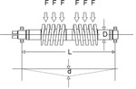 Figure 9. Radial forces in twin screw pumps.
Deflection must be kept to a minimum because greater deflection requires larger clearances, resulting in more slip flow or volumetric inefficiency. Excessive deflection damages the surrounding body and/or contributes to rotating bend fatigue, which ultimately results in shaft breakage. Large diameter shafts and screw root sections are used to maintain minimum deflection.
Depending on the machining direction of the threads (left or right hand) and the direction of shaft rotation, the pump manufacturer can cause deflection in either of the two radial directions, up or down for a horizontal pump. These radial deflection loads are absorbed through externally lubricated antifriction bearings.
Radial loads are proportional to differential pressure across the pump. Higher differential pressure produces higher radial loads or forces. Smaller lead angles of the screw set reduce these radial loads and reduce the flow rate. Larger lead angles increase the flow rate as well as the radial loading. Bearings are usually sized to provide 25,000 or more hours L10 bearing life at maximum allowable radial loading and maximum design operating speed. Because of this pumpage-independent bearing system, twin screw pumps with external timing gears and bearings can handle high gas content as well as light oil flushes, water, etc.
Twin screw pumps are manufactured from a broad range of materials, including 316 stainless steel. When extreme galling tendencies exist between adjacent running components, a slight increase in clearance is provided to minimize potential for contact during upset conditions. In addition, the stationary bores in which the screws rotate can be provided with a thick industrial hard chrome coating that further reduces the likelihood of galling and also provides a very hard, durable surface for wear resistance.
Such coatings do, however, require the capability of inside diameter grinding to achieve finished geometry within tolerances. For highly abrasive services, the outside diameter of the screws can be coated with various hard facings to better resist wear. Among these coatings are tungsten carbide, stellite, chrome oxide, alumina titanium dioxide and others.
Medium and high viscosity operations are not the only regions where multiple screw pumps bring advantages to the end user. Low viscosity combined with high pressure and flows less than approximately 450-gpm (100-m3/h) are excellent screw pump applications. The combination of modest flow, low viscosity and high pressure is a difficult service. This is a typical application for reciprocating pumps in crude oil pipelines.
Reciprocating pumps require pulsation suppression devices in the suction/discharge to avoid excessive vibration on the piping system, which is a potential environmental concern. Ongoing research and development efforts will further extend the capabilities/capacities of these machines, allowing better performance over a broader range of applications.
Multiple screw pumps are uniquely suited to many of the applications in the oil and gas market and offer long term benefits to their users, including higher efficiency, pulseless flow, smaller footprints and equipment that is easily maintained.
References
1 "Oil & Gas Industry Report," Oil & Gas Pump Showcase, Pumps & Systems Magazine, February 2007, p. S4.
