Pumps & Systems, March 2013
Q. How do I determine the NPSH3 for a rotodynamic submersible pump?
A. NPSH3 is the net positive suction head required, in meters (feet) that will cause the total head (or first-stage head of multistage pumps) to be reduced by 3 percent. Four typical arrangements are available for determining the NPSH3 characteristics of rotodynamic submersible pumps. For all arrangements, the flow toward the pump must be uniform and free of undue disturbances. A pump tested with suction piping may require a flow-straightening device before entering the pump. Arrangements for cooling or heating the liquid in the loop may be needed to maintain the required temperature.
In one arrangement (see Figure 11.6.7.2c), the pump is supplied from a closed tank in which the level is held constant. The net positive suction head available (NPSHA) is adjusted by varying the air or gas pressure over the liquid, varying the temperature of the liquid, or both. This arrangement tends to strip the liquid of dissolved air or gas. Testing with a closed loop without the closed tank on the suction side is also acceptable.
In another arrangement (see Figure 11.6.7.2d), the entire pump is mounted in an enclosed tank to allow the NPSH testing to be done without the suction piping connection. The testing for this arrangement is normally performed at a constant flow rate while varying the NPSHA by adjusting the air pressure over the liquid in the suction tank.
In each arrangement, water must be used as the test liquid. Taking the following precautions will minimize aeration:
- No cascading return flow outlets
- Reservoir sized for long retention time to allow air to escape
- Inlet line properly located to prevent vortexing
- Reservoir baffles to isolate inlet from the return line
- Tight pipe joints to guard against air leakage into the system
For more information about NPSH tests for rotodynamic submersible pumps, see ANSI/HI 11.6 Rotodynamic Submersible Pumps for Hydraulic Performance, Hydrostatic Pressure, Mechanical, and Electrical Acceptance Tests.
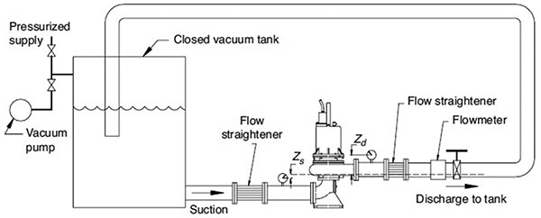
Figure 11.6.7.2c. A pump is supplied from a closed tank with a constant level.
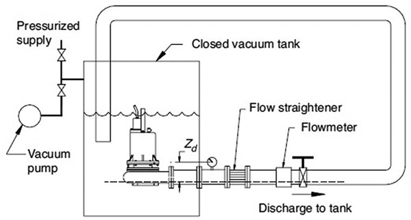
Figure 11.6.7.2d. The entire pump is mounted in an enclosed tank to allow the NPSH testing to be completed without the suction piping connection.
Q. How should I design trench-type wet wells for the intake of rotodynamic pumps, and how are these different from rectangular intake structures?
A. Trench-type wet wells differ from rectangular intake structures by the geometry used to form a transition between the dimensions of the influent conduit or channel and the wet well itself (see Figure 1). An abrupt transition is used to create a confined trench for the location of the pump inlets.
While limited physical modeling work has been conducted on trench-type wet wells, successful applications with individual pump capacities as great as 75,000 gallons per minute (gpm) or 4,730 liters per second (L/s) and installation capacities of 225,000 gpm (14,200 L/s) have been constructed for centrifugal pumps. Axial and mixed flow applications include individual pump capacities of 46,000 gpm (2,900 L/s) and total installation capacities of up to 190,000 gpm (12,000 L/s).
Most applications of the trench-type design have been with the incoming flow directed along the wet well’s long axis (coaxial). Physical model studies shall be conducted for any installation with individual pump capacities exceeding 40,000 gpm (2,520 L/s) or stations with capacities greater than 100,000 gpm (6,310 L/s).
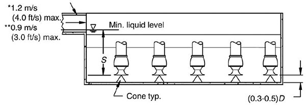
Figure 1. Trench-type well
Q. What information is available regarding starting torque requirements for reciprocating power pumps with liquid bypass?
A. Using reciprocating power pumps requires carefully considering their starting and running torque demands. These affect the selection of driver motors, motor starters, engines, gear reducers, belts or chain drives, couplings, and universal joints. These loads’ effects on an electrical distribution system require thought, especially for a large pump.
For starting the pump with a liquid bypass, the operator manually opens a bypass valve or a power-actuated dump valve opens automatically. This bypasses the liquid during starting and stopping. A check valve in the discharge line remains shut if the bypass (dump) valve remains fully or partially open (see Figure 6.47).
The liquid pressure exerted on the plungers (or pistons) is largely caused by liquid mass and friction. When correctly sized, the bypass valve and piping cause low back-pressure. Relatively small torque is required while bypassing the liquid to a tank. With liquid bypass, the total starting torque requirement is mainly related to the mechanical inertia of the pump, couplings, gears and motor rotor. These components are heavy and require substantial starting torque. The liquid in the pump suction line and in the bypass line must be accelerated from standstill to full liquid velocities.
The torque needed to accelerate the entire mechanical hydraulic inertia system depends on the inertia of all the moving parts—including the liquid, the rate of acceleration and the total system friction. The rate of acceleration is important, and the starting torque is directly proportional to it. Peak torque is inversely proportional to the time duration of acceleration.
A few pumps are provided with mechanical suction valve unloader devices. They reduce the total starting torque required to accelerate the mechanical items—the pump crankshaft, gears, couplings, etc. They stop liquid pumping action by mechanically holding open the pump’s suction valves, allowing the liquid inducted into each liquid cylinder to be delivered back into the pump suction. Because no liquid pumping occurs, the driving machinery does not need to apply torque to accelerate the liquid. Only the torque to overcome mechanical inertia and friction is needed during the start.
After the pump and driver have reached full speed, the suction valve unloading devices are retracted, and normal pumping action commences. At this point, the driver must supply additional torque to accelerate the liquid system and meet the total running torque requirement caused by discharge pressure. P&S
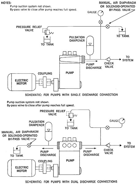
Figure 6.47. Schematics of liquid bypass systems