
Pumps & Systems, July 2013
The purpose of surface finish is to allow a gasket to conform to and seal the flange face. “Sealing Sense” in the April 2008 Pumps & Systems discussed the importance of ensuring that the choice of gasket and surface finish work together to maintain the appropriate level of sealing stress on the gasket. This update identifies some of the typical damage that occurs to a flange face, what the effect is and discusses a way to identify the practical limits for them.
Gasket Sealing
A gasket’s role is to seal the space between the mating surfaces of a flange connection. This is accomplished when the bolt load compresses the gasket to a level of tightness that allows it to fill the gap between the mating faces and fill the small imperfections in the sealing surfaces.
With proper flange design and gasket installation, the stress on the gasket will be sufficient to create a barrier between the pressurized side of the gasket and hold it securely in place. All the paths of leakage are effectively blocked between the gasket and flange. However, what if portions of the flange face are damaged? Will the flange leak if used or should the end user replace it? Let’s look at flange face damage and its potential effect on gasket sealing.
Types of Damage
Over time and for any number of reasons, damage can occur to flange faces. Each damaged area will tend to create a potential leak path that the gasket must try to seal.
Some common types of flange surface damage, their characteristics and possible causes are listed below:
- Scratches—This type damage is narrow and elongated with sharp, shallow bottoms. However, depending on the force that created them, they can be deep. Frequently, this type damage is created by a sharp object dragging across the flange face. These objects may include the bristles of a wire brush or a tool, such as a chisel.
- Gouges—These are wide and elongated with blunt, rounded bottoms and are created by a dull object dragging across the flange face. Gouges can be caused by objects—such as a screwdriver, flange jack or chisel.
- Pits—This damage is usually small, somewhat rounded areas of concentrated material loss created by corrosion. Often, pits occur in clusters or groups.
- Dents—This type damage can be sharp or blunt non-elongated areas caused by some form of impact. Dents sometimes result from equipment collisions caused by positioning the mating flanges using cables and rigging.
The most common events that create surface finish damage are indentations that occur from removing previously used gasket material from the sealing surface. Tools, such as chisels or screw drivers, should be avoided. A brass wire brush is preferred.
Damage Impact
What the damage types have in common is that they reduce the sealing tightness of the gasket against that particular (damaged) area of the flange face. If these defects are small and few, the leak tightness of the bolted connection will not be significantly impacted. If a defect is large (especially across the radial direction of the flange face) or several defects are grouped in a small area, the leakage path can exceed the ability of the gasket to block it, and leakage can occur.
Whether the gasket can successfully seal these damaged areas depends on their size, depth, orientation and number. The question then becomes, how large is too large, or what is the limit on the number of small defects in a single area? Is the flange “fit” to be returned to service?
In 2010, the American Society of Mechanical Engineers (ASME) addressed this issue in its standard, Guidelines for Pressure Boundary Bolted Flange Joint Assembly, ASME PCC-1-2010. This standard provides guidance for several important flange considerations. Appendix D of the standard includes information that specifically addresses issues of flange surface condition.
Appendix D includes figures and tables that provide guidelines for setting allowable limits on flange face defects. Specifically, it shows how to assess damaged portions of a flange face by taking measurements of the defective areas (see Figure 1).
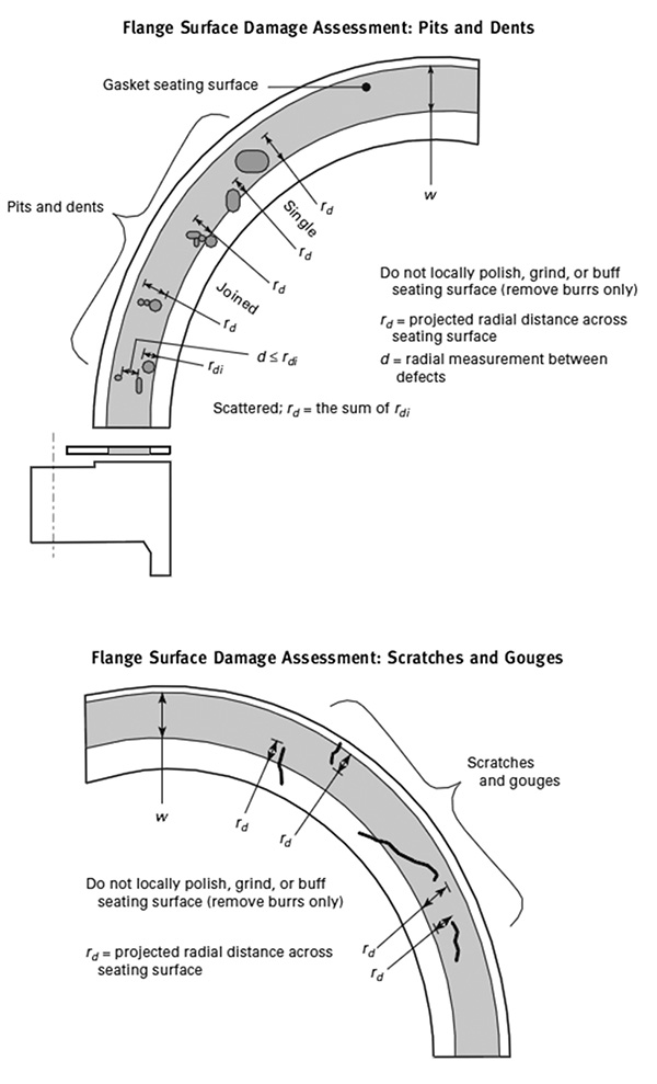
Figure 1. Flange surface damage assessment. Reprinted from ASME PCC-1-2010, by permission of ASME. All rights reserved.
With these measurements, Table 1 can be accessed to determine the applicable limit for a particular type of damage. Limits are established by determining the effective length (in the radial direction) and matching it to the depth of the same defect. The respective limit will depend on the type and category of gasket being used in the bolted flange connection.
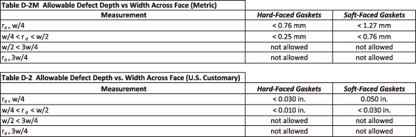
Table 1. Allowable defect depth versus width across a face. Reprinted from ASME PCC-1-2010, by permission of ASME. All rights reserved.
Soft Gaskets Versus Hard Gaskets
The ability of a gasket to seal a damaged area is similar to how a gasket seals against the surface finish of the flange. It depends on how conformable the gasket is to the particular area of the flange face surface. Soft gaskets are more capable of filling (and therefore sealing) a defective area than hard gaskets. For this reason, the appendix divides its guidance into two categories of gaskets: soft gaskets and hard gaskets. Each type has a different limit.
For example, if a single gouge has a radial length of less than one-fourth of the gasket width, the permissible depth of the gouge is 0.050 inch for a soft gasket. The identical gouge on a hard gasket has a depth limit of only 0.030 inch. See Table 1 for additional information. For any damage type, end users must correctly categorize the type of gasket used and match it to the respective table provided in the standard and noted in this article.
Flange Flatness Limits
The flatness of the flange also affects a gasket’s ability to seal. A lack of flange flatness can also be considered damage. This can occur because of excessive loads on the flange or as the result of errant machining of the flange surface. Soft gaskets will also tend to conform to and seal areas of poor flatness better than a hard gasket. Again, the tolerance of a lack of flatness depends on whether the gasket is soft or hard.
For example, a hard gasket can seal a lack of flatness in the radial direction that is less than 0.006 inch. The limit for a soft gasket is 0.01 inch. Guidelines are also included that set limits on a lack of flatness in the circumferential direction. See Table 2 for additional information.
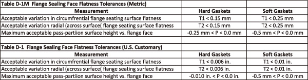
Table 2. Flange seating face flatness tolerances. Reprinted from ASME PCC-1-2010, by permission of ASME. All rights reserved.
Repair, Replace or Accept?
The best policy is always to protect the flange faces from any form of damage. Plants should also establish a quality assurance program that verifies the flatness of new flanges and provides training for maintenance personnel on the acceptable limits as provided in the guidance of ASME PCC-1-2010, Appendix D. This guidance provides the best available information for field personnel to determine whether to accept flange face damage, repair it or replace it.
Author’s Note: ASME reviews and rewrites its standards every three years. PCC-1-2010 has recently undergone its review and rewrite and is currently out for ballot. Once approved via the ballot process, PCC-1-2013 is expected to be published. The new document will offer further clarification regarding the details in this article. However, minor revisions to the information offered in this “Sealing Sense” are expected. P&S
