
As operators of pumping equipment become more focused on the safety, reliability and environmental impact resulting from shaft seal leakage, dual mechanical seals have become more prevalent in the industry. A dual mechanical seal offers a second (outer) seal to contain the pumped fluid by creating a cavity or chamber between the inner and outer seal that can be filled with a fluid. When this fluid is unpressurized, it forms a buffer between the pumped fluid and atmosphere and is commonly referred to as a buffer fluid. When pressurized, it forms a barrier between the pumped fluid and atmosphere and is known as a barrier fluid.
Although mechanical seal designs are available in configurations that use either a liquid or a gas as a barrier fluid, the following discussion focuses on liquid buffer and barrier fluids only. In addition to separating the pumped fluid from the atmosphere, liquid buffer and barrier fluids lubricate the mechanical seal and transport frictional heat and absorbed heat from the mechanical seal to a heat exchanger. This controls the fluid’s temperature and lubricating properties.
Buffer & Barrier Fluid Supply
Buffer/barrier fluid can be stored, monitored and delivered using many methods. Each is identified by a piping plan number that describes the minimum requirements of each system. The most commonly referenced piping plan originates from the American Petroleum Institute’s standard API 682.
Unpressurized Systems
A Plan 52 system (see Figure 1) provides a reservoir that stores the buffer fluid. Supply and return lines are connected to the mechanical seal and circulation of the buffer fluid is achieved by an internal circulating device (pumping ring) within the mechanical seal. The vapor space above the buffer fluid in the reservoir is vented to atmospheric pressure typically via a flare or vapor recovery system. The reservoir can be instrumented to measure the liquid level and pressure in the reservoir. Ports are fitted to the reservoir to facilitate maintenance activities—such as inspection and cleaning or refilling and draining the buffer fluid. Cooling is accomplished using an internal heat exchanger.
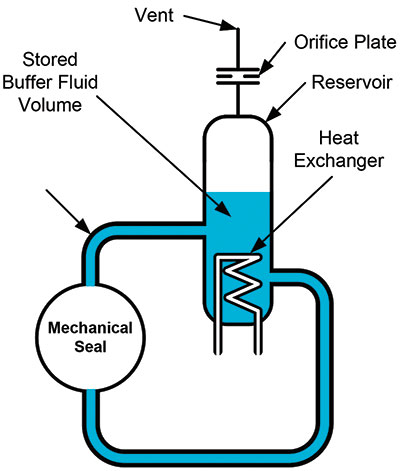 Figure 1. Simplified schematic of a Plan 52 system
Pressurized Systems
Pressurized dual seal systems contain the same essential components as an unpressurized system. However, they also contain a way to pressurize the barrier fluid. The following plans may be used for pressurized dual seal systems:
- Plan 53A—A pressurized gas blanket in the reservoir pressurizes the fluid. Nitrogen is normally used and the pressure is controlled via a pressure regulator (see Figure 2). The barrier fluid is in direct contact with the pressurized gas.
- Plan 53B—Pressure is generated as a nitrogen-filled bladder is compressed by the addition of barrier fluid into the bladder accumulator. The bladder prevents direct contact of the pressurized gas with the barrier fluid.
- Plan 53C—A pressure amplifying piston uses pressure from within the pump (typically the seal chamber) to amplify the barrier pressure by the ratio of the area on each side of the piston. The barrier fluid is not exposed to any pressurized gas.
- Plan 54—An external system is used to pressurize and circulate the barrier fluid. A Plan 54 system can be broadly classified into two groups: closed- and open-loop systems. In closed-loop systems, the barrier fluid is stored in a large reservoir and pumps pressurize and circulate the fluid. In open-loop systems, a compatible process stream is used as the barrier fluid and is circulated through the mechanical seal and returned to another point downstream in the process.
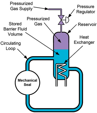 Figure 2. Simplified schematic of a Plan 53A system
Important Characteristics of a Buffer/Barrier Fluid
Several critical properties of a buffer or barrier fluid must be considered when making a selection. An ideal buffer or barrier fluid will have the following properties:
- Safe to use, handle and store
- Compatible with seal materials
- Not a volatile organic compound, volatile hazardous air pollutant or other regulated compound
- Good flow qualities at operational temperatures (including very low temperature service)
- Nonflammable
- A stable liquid at ambient temperatures
- Good lubricity
- Non-foaming when pressurized
- Good heat transfer properties
- Low gas solubility
- Compatible with process fluid
- Inexpensive
Buffer/Barrier Fluid Families
Liquids that have characteristics suitable for use as buffer and barrier fluids can be broadly classified into the following:
- Water and glycol solutions
- Petroleum-based hydraulic and lubricating oils
- Alcohols
- Synthetic hydraulic oils
- Kerosene and diesel fuels
- Heat transfer fluids
Typical physical properties of fluids in these categories are listed in Table 1 with a suggested service temperature range.
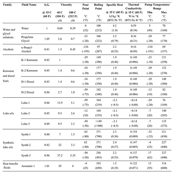 Table 1. Typical buffer and barrier fluid properties
Water
Water offers several benefits as a buffer/barrier fluid. Its thermal conductivity is about three times greater than oils and its specific heat is about twice that of oils, so it is good at transporting heat away from a mechanical seal. Water is inexpensive, easy to handle and store, has few seal material compatibility issues and is nonflammable. It is also compatible with many aqueous pumped solutions. Its viscosity is generally around 1 centistoke at moderate temperatures which offers low resistance to flow in the barrier system.
However, the viscosity becomes low at elevated temperatures limiting its effectiveness as a lubricant for the mechanical seal faces. Water is also susceptible to freezing during the winter months. This results in a narrow window of service and environment temperatures in which water can be used.
Oils
Generally, oils can be used in a much wider range of service temperatures. Compared to water, oils offer greater fluid stability at elevated temperatures and are not susceptible to freezing. They also provide excellent lubrication of the mechanical seal faces and, therefore, have the potential to offer longer seal life. Few compatibility issues with mechanical seal materials exist.
Oils are available in a wide range of types, compositions and viscosities. Traditional oils used in the industry include turbine oils and automatic transmission fluids. However, performance as buffer and barrier fluids has not been as successful as other oils, primarily because of the complex mixture of additives in these fluids.
Good performance can be achieved from oils with viscosity below that of ISO Grade 32 oils. High viscosities can result in damage to the mechanical seal faces, particularly when carbon is used as a face material. Paraffinic-based oils also generally perform better than naphthenic oils while synthetic oils offer even better performance. Synthetic lubricants specifically developed for use as a buffer/barrier fluid are now available in the marketplace and offer excellent performance. However, this performance is achieved at the sacrifice of cost.
Next Month: What are pressure seals, and how do they work?
We invite your suggestions for article topics as well as questions on sealing issues so we can better respond to the needs of the industry. Please direct your suggestions and questions to sealingsensequestions@fluidsealing.com.
