


Editor's Note: This is the fifth in a six-part series on dry gas seals. For other articles in this series, click here
Fifth of Six Parts
This article in the series focuses on choosing the major components for a reliable dry gas seal panel and covers seal supply gas control, seal health monitoring, primary seal leakage and vent lines.) The dry gas seal panel (see Figure 1) is a critical part of a dry gas seal system. Poorly designed panels will consume more utilities; initiate nuisance alarms; shutdown compressors unnecessarily; and increase line, filter and heater sizes to accommodate unnecessary flow. These conditions will also result in higher volumes of recycled gas that can add up to a major waste of energy.
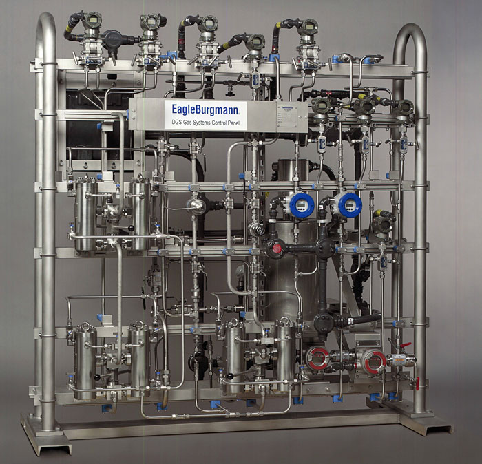 |
| Image 1. The dry gas seal panel is a critical component in a dry gas seal system. |
An ideal system provides the required flow to a dry gas seal to ensure reliability and prevent the release of process gas. If a seal fails, the released gas could be detrimental to equipment or personnel within the area. Attention to certain factors can prevent this risk. However, only the combined efforts of rotating-equipment experts and seal vendors can produce a reliable and safe dry gas system.
Seal Gas Control
As discussed in “Choosing Process and Separation Seals” (Pumps & Systems, July 2012), the velocity at which gas flows across the process seal ensures that no process gas will backflow toward the seal. When dry gas seals were first installed, differential pressure was measured and maintained across the process seal, which provided adequate seal gas flow. To achieve the differential pressure, the control valve was set to operate most effectively—typically between 5 and 10 psid. Effectively maintaining the flow when differential pressures were below 5 psi was challenging for the pressure control valves, especially as changes occurred in the sealing pressure. To solve this, higher settings were used along with higher seal gas flows.
The differential pressure control method ensured flow across the process seal, but at what cost? Using differential control provides five to 10 times more flow compared to a flow control system, meaning the filters and conditioning system must be designed for five to 10 times more capacity than is required.
A flow-control system provides the best way to achieve the right flow/velocity across the process seal. By maintaining the correct flow and ensuring that the flow measurement device has been engineered correctly, the velocity of gas across the process seal will be achieved regardless of pipe length or configuration. To maintain the specified flow to the dry gas seal, a control valve is required for the seal supply line, and a flow-measuring device is needed to verify that flow is present at all times.
Old worries—guessing at line losses or wondering whether the differential pressure setting was sufficient—will no longer cause system setbacks. If the required flow is attained and the flow measurement device has been engineered correctly, sufficient velocity across the process seal will be achieved. For the seal supply line, a control valve is required to maintain the specified flow to the dry gas seal and a flow-measuring device is needed to verify the flow is present at all times.
A filter is required in a seal supply line. A coalescing filter should always be used, since it can handle both liquids and particles. The chosen filters should have no problem removing aerosols or particles up to 0.3 percent by volume in the gas stream to a cleanliness of 3 micron absolute. Dual filters in parallel should be used, allowing maintenance to be performed without interrupting flow to the dry gas seal.
For all applications, the seal gas composition must be analyzed to ensure that it arrives at the seal and passes between the faces with no condensates that may interfere with the seal’s operation. The amount of allowed particle contaminants should also be identified to ensure that standard filters are not overburdened.
System alarms will identify high filter differential and low or high seal gas flow. The high filter differential pressure alarm indicates if filter elements need replacing. Since these are dual filters, the standby filter can be put into service and the dirty filter changed without flow interruption. A low-flow alarm will determine if the seal receives insufficient seal gas and identify the possibility of seal contamination and failure. A high-flow alarm indicates if the control valve has failed, since seal gas control valves are typically designed as fail-open to ensure that seal gas flow is never cut-off.
Seal Health Monitoring
The next concern is monitoring the dry gas seal’s health. The seal health is monitored by seal leakage, which is defined as the amount of gas passing between the seal faces. Seal leakage will change based on the seal’s size, speed, operating pressure, operating temperature, and gas composition. A port in the compressor either vents the leaking gas to a flare line or a vapor recovery system, or routes it to a safe location and releases it to the atmosphere. A flow measurement device assesses the seal leakage as the gas flows through the vent line. An increase in vent line flow results from an increase in leakage between the seal faces, indicating a problem with the seal. When the flow rises to a level 2.5 to 5 times normal leakage, an alarm will notify the operator the seal is failing. Should the seal leakage increase 5 to 10 times normal levels, seal failure will occur, and a compressor shutdown and venting will be initiated.
The primary and secondary seals have different operating conditions; therefore, the primary seal leakage will be different than the secondary seal leakage. When purchasing a dry gas seal, guaranteed leakages (see Figure 1) are provided for both the primary and secondary seal. This information helps with designing the leakage monitoring system and identifying a primary seal failure. By knowing the identified leakage and where the primary vent line will be connected, a system can be set up to effectively measure the primary seal leakage.
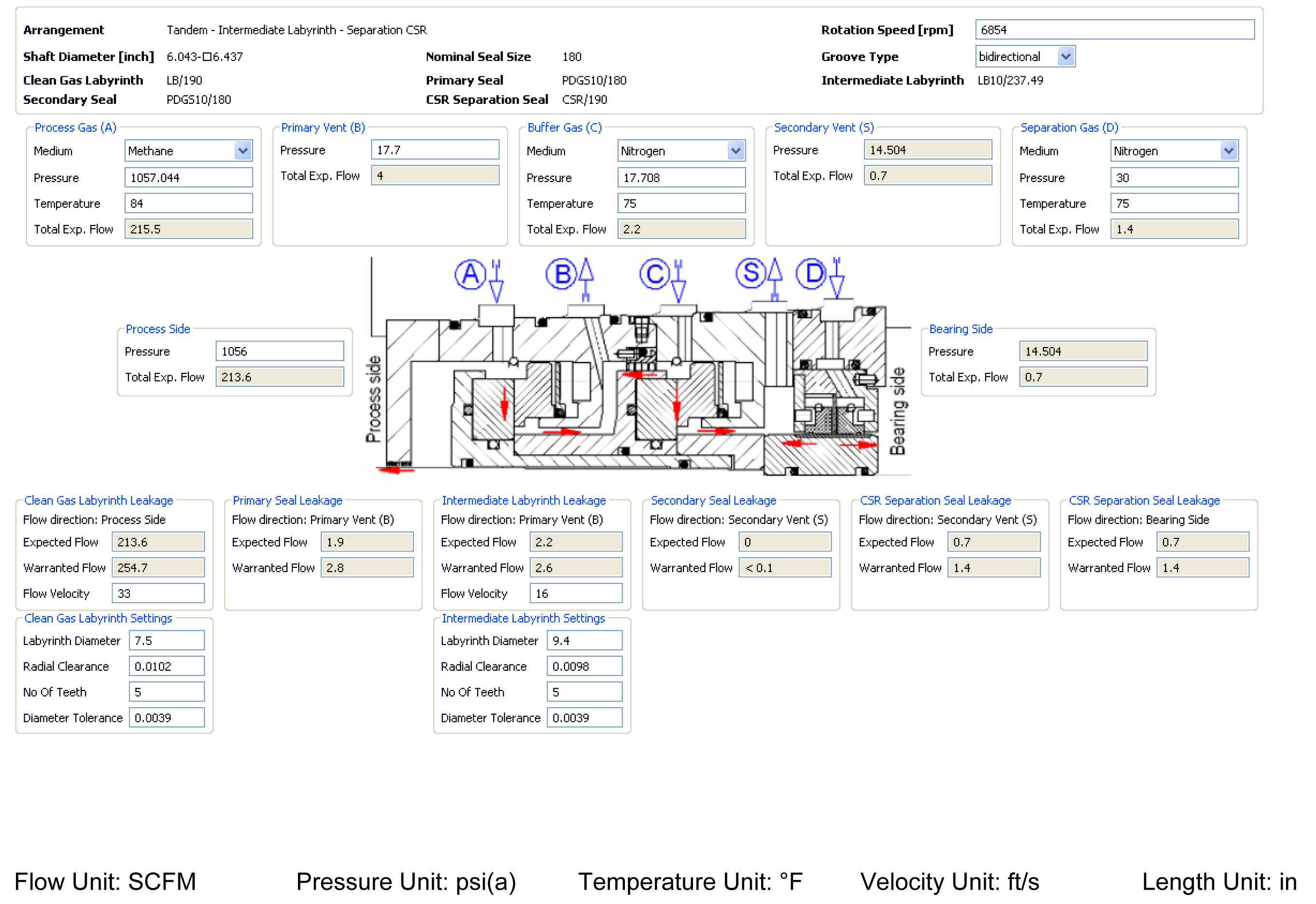 |
| Figure 1. This chart shows seal leakage calculations, based on operating conditions, which are necessary for designing an effective leakage monitoring system. |
Primary Seal Leakage
For primary seal leakage, the debate has always been whether to use pressure or flow measurement to identify seal failure. Economical yet unreliable, using pressure measurement to detect a seal failure requires an orifice to develop a backpressure. If the seal leakage increases, the pressure upstream of the orifice also increases. When sufficient backpressure is exerted on the orifice, a high-leakage alarm sounds. If the pressure continues to rise (flow increases through the primary seal), a seal failure is indicated, and the compressor will shut down and vent. Whether an immediate or controlled shutdown occurs depends on the application.
When the primary vent line goes to the atmosphere, pressure indication on the vent line is the same as the flow measured by a differential pressure across an orifice, making it feasible to identify the seal leakage flow. This design does not provide an actual flow indication, so the orifice size and pressure must be used to convert the readings to a flow. This is a disadvantage, because the seal operating condition cannot be quickly assessed. The flare line presents another disadvantage. If the primary vent goes to the flare line, the flare pressure downstream from the orifice will cause the pressure build-up across the orifice to vary. For this application, the vent monitoring system’s design must incorporate the maximum possible flare pressure, so false seal failures/compressor shutdowns do not occur when the flare pressure increases. A system designed with pressure as the shutdown method will result in higher leakage flows to initiate a shutdown.
Straight vent pressure indication also fails to accurately assess changes in the seal when the vent and flare lines are connected. With enough cross-reference information comparing flare pressures to vent pressures, a rough trend of the seal leakage or its health can be produced, but a properly designed system can better trend seal health. When a seal failure does occur, using a transmitter to measure the differential pressure across an orifice and converting this to a flow provides the most effective method of monitoring seal vent flow, trending seal leakage, indicating seal health, initiating alarms and shutting down and venting the compressor safely if required.
The other important component in the primary vent is a way to vent excess pressure in the event of a seal failure. When a seal fails, the orifice in the vent line restricts flow, causing high pressure to build in the primary vent cavity. This failure creates a dangerous situation in which, if a secondary seal failure occurred, a higher pressure could form in the secondary vent and force process gas into the bearing cavity—increasing the risk of explosions, fires and toxic gas released to the atmosphere.
Either a rupture disk or a relief valve can provide a way to manage high primary vent pressure when it does occur. However, because of problems associated with using a rupture disk, a relief valve provides a more reliable system. Even a pressure relief device may not be needed for pressures less than 100 psi, since a double seal works best at these pressures.
Vent Lines
For primary and secondary vent lines, preventing and managing seal failures requires protection against seal contamination and back pressure and a sufficient line size to vent gas when a seal fails. Many seal failures have occurred due to poorly designed vent lines, incorrectly located check valves, incorrectly plumbed lines or poor atmospheric vent designs. Poorly designed atmospheric vents allow insects or rainwater to enter the line and contaminate the seal, reducing reliability and possibly causing a seal failure. When the vent line is incorrectly connected to a flare line, contamination from the flare line can enter the vent line and seal.
A screen placed over the end of an atmospheric vent line will prevent insects/debris from entering the line. While venting, the end of the vent line should be directed downward to prevent contamination building up on top of the check valve. When connecting to a flare line (see Figure 2), the check valve should be in the downward portion of the piping or tubing where it connects to the flare header. This ensures that, when the check valve opens, nothing can build up on top of the check valve and flow down into the seal.
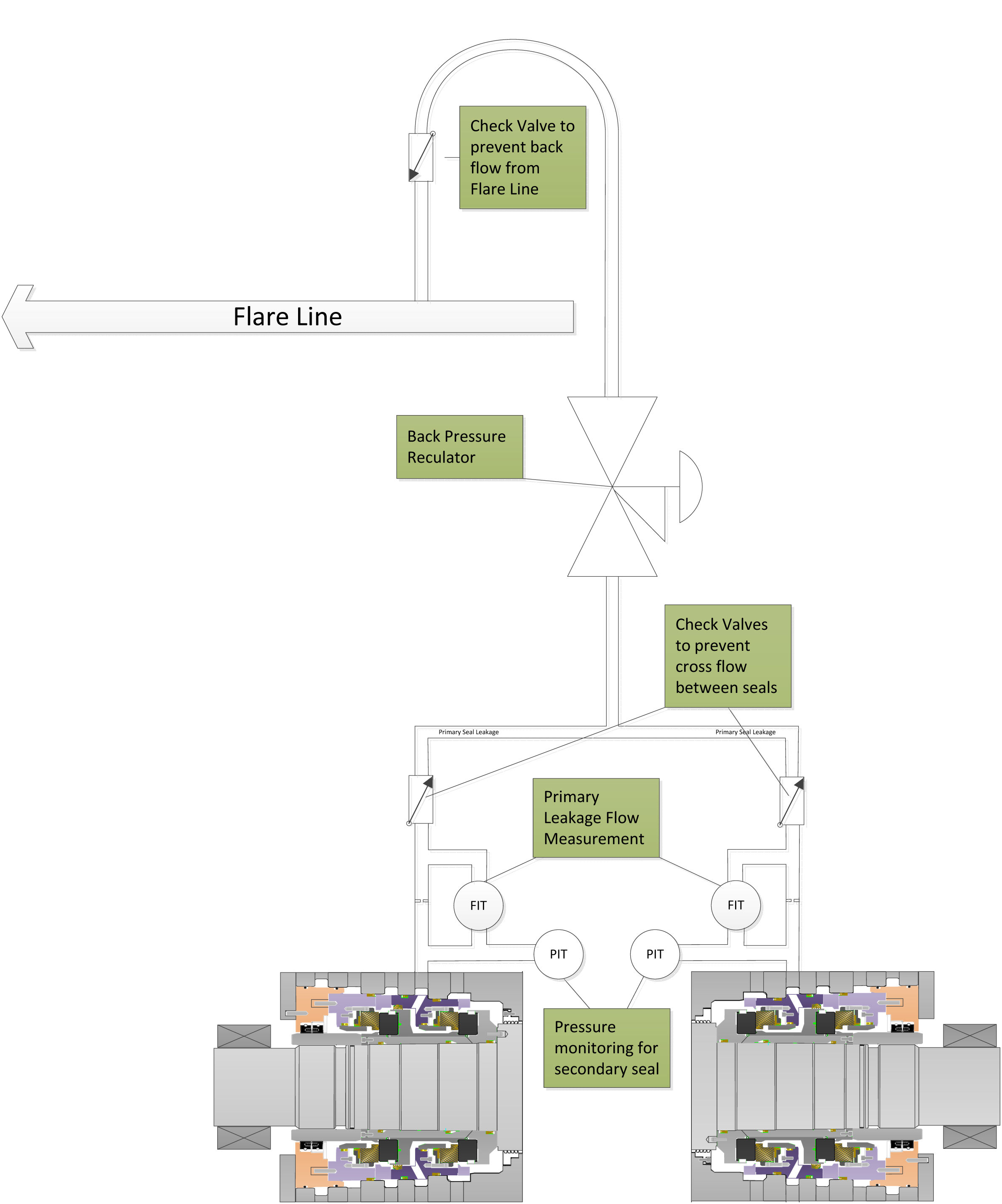 |
| Figure 2. When connecting to a flare line, correct placement of the check valves is critical to ensure seal reliability. |
The compressor’s vent lines and porting must be accurately sized to minimize pressure cascading through the dry gas seal to the separation seal should a catastrophic seal failure occur. The correct pipe and porting diameter or area of flow path will reduce gas pressure in the primary and secondary vent cavity. Vent lines and porting must be properly sized to prevent a higher pressure in the secondary vent than in the primary vent during normal operation. Even though normal flow may not warrant a large vent size, a seal failure requires a large vent pipe to minimize secondary vent cavity pressure.
Secondary Seal Health
Recently, an undetected secondary seal failure highlighted the industry’s need to promote the accurate monitoring of the secondary seal’s health as an important part of the dry gas seal system. To addres this additional devices must be placed in the primary vent line to create a pressure on the secondary seal, to effectively monitor its health and increase reliability.
Check valves, with specified cracking pressures and backpressure regulators, are common and reliable devices to produce backpressure in the primary vent line for applications with sealing pressures of 100 psi and greater. If a tandem seal is used for applications less than 100 psi, the system design must include precautions that reduce the risk of the primary seal becoming reverse pressured. Ideally, a double seal should be used in these applications.
Why not measure the flows in the secondary vent just like the primary vent? The challenge is that the vent line also contains nitrogen or air flowing from the separation seal. An increase in flow from the separation seal into the secondary vent can occur, producing a false indication of secondary seal failure. Furthermore, flow-measuring devices used to detect small changes in the secondary vent flow create restrictions. As the secondary vent line’s main purpose is to remove as much gas as possible during a catastrophic failure, any restrictions in this line are dangerous.
Therefore, a pressure held in the primary vent is the best approach for monitoring the secondary seal. If the pressure in the primary vent is reduced or lost, this means something has happened to the secondary seal. This requires a pressure transmitter—when the pressure decreases, an alarm sounds to indicate a possible problem with the secondary seal. Depending on the application, the operator must determine the risks of continuing to run the compressor.
For tandem seal applications, where a secondary seal gas is not used, building pressure in the secondary vent may be difficult. Seal vendors can suggest alternative ways to manage these applications.
Secondary Seal Gas
Secondary seal gas is used for a tandem seal with intermediate labyrinth. Typically, the secondary seal gas is nitrogen, but any other inert gas can be used. The secondary seal gas assists with flushing the primary leakage to the flare or vapor recovery. With the intermediate labyrinth and a secondary seal gas, the leakage across the secondary seal will only be the secondary seal gas. A reliable secondary seal gas system will have a differential pressure regulator, orifice and flow measurement device.
For secondary seal gas, the typical design uses a pressure regulator with a set pressure upstream of the orifice. The pressure prior to the orifice is set to manage maximum anticipated flare pressure. This results in a larger flow of gas during normal operating conditions to manage events when high flare pressure will occur, meaning that a higher than necessary amount of nitrogen is usually consumed. Using a flow control method will reduce the amount of nitrogen consumed (see Figure 3).
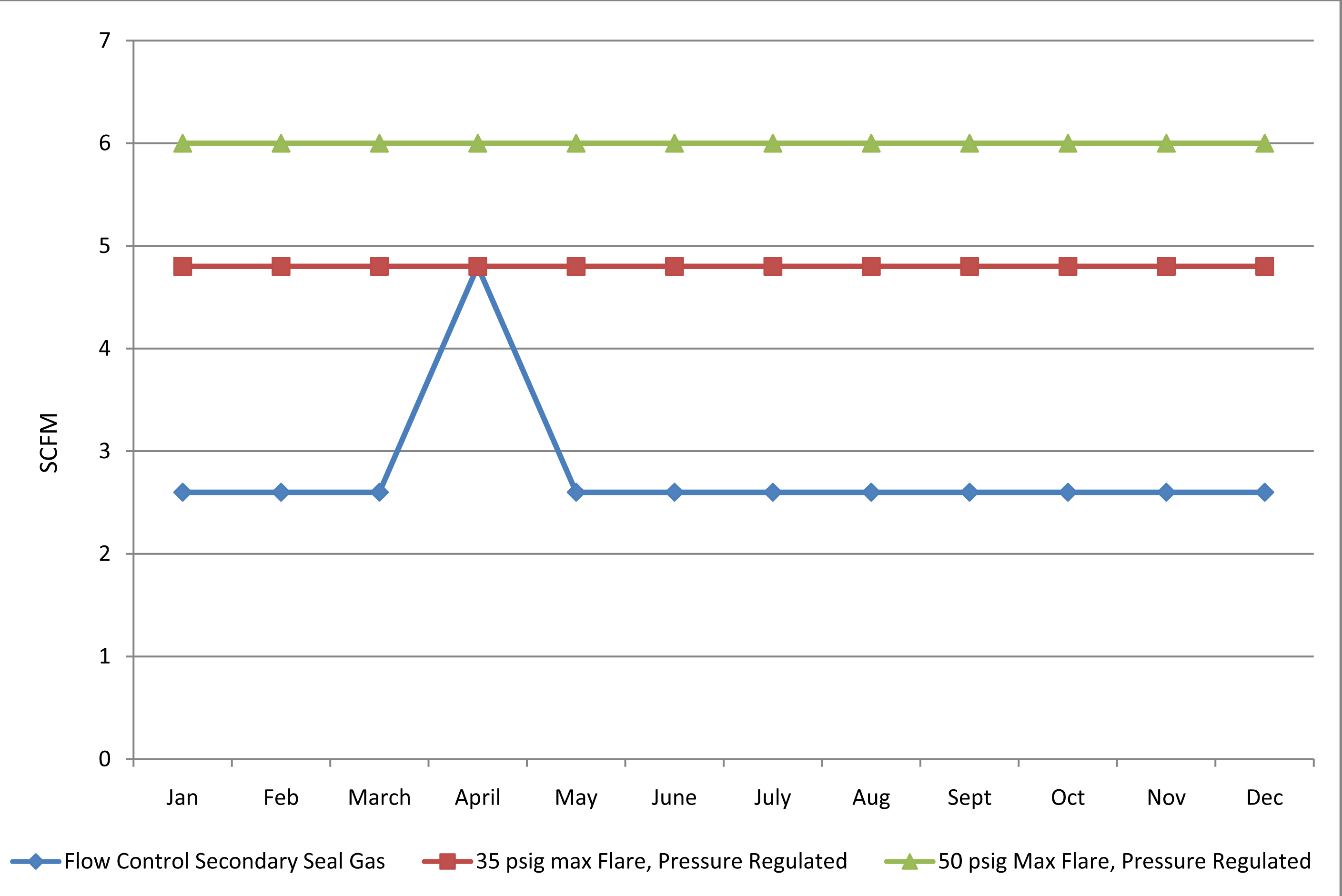 |
| Figure 3. This graph depicts the consumption of secondary seal gas with a flow control design compared to a regulator and fixed orifice configuration. |
Typically, this method uses a differential pressure regulator and an orifice. The regulator senses the pressure upstream of and downstream from the orifice. This allows the regulator to be set at 10 psid and the orifice sized to provide a specified flow with the 10 psid. As the flare pressure increases, the pressure allowed through the regulator increases. The 10 psid across the orifice is maintained, increasing the flow and maintaining a minimum 5-meter-per-second flow across the intermediate labyrinth, resulting in a more efficient secondary seal gas system that consumes less nitrogen during normal operation.
Secondary seal gas systems will have a flow-monitoring device with an alarm for low or lost seal gas flow. Some applications will use a delayed shutdown, to allow time to resolve the loss and reinstate the secondary seal gas flow. The hazards created by the loss of secondary seal gas supply, as determined by the hazardous and operability study (HAZOP), dictate whether to use an alarm or delayed shutdown.
Secondary Vent
Monitoring the secondary vent is only required for monitoring secondary seal health or if using a controlled shutdown on the compressor. As indicated above in the “Secondary Seal Health” section, monitoring the secondary seal health via the secondary vent is not recommended due to the method’s unreliability. A controlled shutdown would require continued compressor operation when a primary seal failure has occurred, so the process can be safely shutdown—minimizing possible associated costs. Any design for monitoring the secondary vent flow must produce minimal backpressure in case the secondary seal were to fail after the primary seal has failed. Excessive backpressure in this vent will result in process gas flowing into the bearing cavity—a dangerous situation that could result in an explosion, fire or personnel exposure to toxic gas. If the secondary vent requires monitoring, use a flow-monitoring device, which has a high-flow alarm, a shutdown on a higher flow and an additional relief valve to bypass any restrictions if necessary.
The secondary vent should have a low-point drain on the compressor that is manually monitored for liquids on a regular basis. The presence of liquids indicates that the separation seal is not operating effectively, and the problem should be corrected to prevent a seal failure. Some systems have an automatic drain, but this eliminates the ability to identify oil in the drain line and poses problems to system reliability. A sight glass is ideal for this application allowing operators to see if liquid/oil is present in the drain, but it must be provided with the appropriate pressure rating and monitored on a regular basis.
Separation Seal Supply
As discussed in “Choosing Process and Separation Seals,” an axial end-face separation seal is the best separation seal to use. The critical components in a separation seal system are a differential pressure regulator, a differential pressure transmitter and a pressure transmitter.
A differential pressure regulator regulates the separation seal supply-gas pressure, so the seal pressure is always higher than the secondary vent cavity pressure. If a catastrophic seal failure occurs, the pressure to the separation seal increases and prevents the process gas from entering the bearing cavity. The differential pressure regulator allows the maximum nitrogen pressure to be used for preventing the process gas from entering the bearing cavity. A single differential pressure regulator can be used for both seals. If a catastrophic seal failure occurs, one seal may consume more nitrogen than the other but only for a short time.
A differential pressure transmitter identifies the differential pressure between the separation supply pressure and the secondary vent. Ideally, the reference line for the secondary vent should be from the vent cavity in the compressor and not the vent line. A pressure drop from the cavity to the line will occur when high flow is present, so a secondary vent connection will not provide a true indication of pressure. In addition, this transmitter will be used to initially set the differential pressure being supplied to the separation seal.
A pressure transmitter recognizes if pressure is present in the separation seal supply system and when the pressure increases. Because oil cannot migrate through the axial end-face seal without separation gas, it does not require separation gas in a standstill condition. Rather than a permissive signal to start the lube oil pump, the signal is provided when the compressor is started. This prevents issues when lube oil is warmed prior to the compressor start, a common cause of dry gas seal contamination.
The alarms for this system are low pressure, high pressure, low differential pressure and high differential pressure. The low-separation supply pressure alarm indicates a loss of nitrogen pressure and provides a delayed shutdown if the separation supply is lost for a long time. A high-pressure alarm identifies a catastrophic dry gas seal failure or a failed differential pressure regulator. A low differential pressure alarm indicates high pressure in the secondary vent or loss of separation supply. The high differential pressure alarm indicates a failed differential pressure regulator.
The sixth and last article in this series will discuss conditioning systems and boosters.