
Editor's Note: This is the second in a six-part series on seals. For other articles in this series, click here.
Proper seal choice is critical for optimal compressor operation.
The focus of this installment is how to choose the proper seal features to ensure a reliable dry gas seal system for optimal compressor operation. It covers the improvements made to dry gas seals from the original dry gas seal design and how these improvements offer a more reliable dry gas seal.
To guarantee optimal dry gas seal operation, the gap between the rotating seat and the stationary face must be maintained at 150 to 200 micro-inches. To maintain this gap effectively, the rotating seat and stationary face materials, groove geometries and dynamic secondary sealing designs must be considered in the seal design to produce a seal that will operate reliably.
Seal Seat & Face Materials
Choosing the correct material for seal faces and seats is critical to managing the changing conditions in compressor applications and for minimizing damage to the seal and the compressor.
Tungsten Carbide
Tungsten carbide was the original material of choice for the rotating seats in dry gas seals. Tungsten is very tough and has the ability to handle high-applied loads without deforming the material. However, tungsten carbide is not problem-free. When it fails, it can cause significant damage to the seal and the compressor’s rotor. Tungsten is also a heavy material. For rotating applications, the hoop stresses applied to the material are substantial, resulting in limitations for applications at higher speeds.
.jpg)
Figure 1. Comparison of synthetic diamond-like carbon and crystalline diamond coating
Silicon Carbide
As the requirements for higher speeds continue to increase for new applications and compressor designs, other materials were considered for optimal dry gas seal operation. Silicon carbide has proven to be a better material for rotating seats in dry gas seals. It exhibits fewer problems when heat is generated by contact or liquid contaminants between the seal face and seat. Silicon is also a lighter material than tungsten and produces lower hoop stresses, so it can be used for higher- speed applications. Since silicon is a brittle material, more caution is required when handling it. When properly applied in the seal cartridge, it has not shown any causes for concern.
Stationary faces were originally made of carbon graphite, which made them more economical to produce, but temperatures and pressures affected the ability of the material to maintain the flatness of the seal face. Again, silicon carbide was a more suitable material for the application. Silicon carbide had the same material properties as the rotating seat, so deflection and changes in thermal growth were similar and enabled higher constancy in maintaining a parallel seal gap.
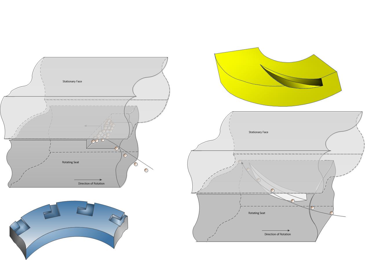
Figure 2. Groove Geometries: Comparison of (specified-depth) edged groove and (three-dimensional) tapered grooves.
Diamond Seal Material
Since both the rotating seat and stationary face are made of the same materials when using silicon carbide, a diamond-like coating (DLC) of 35 to 50 micro-inches can be applied to the stationary seal face providing lubricity and hardness to minimize damage when the seal face and seat contact one another. This works well for most applications, but because of the thin layer of coating, any hard material larger than the seal gap will damage the seal face or seat as it passes between them.
For slow-roll applications, the secondary seal face and seat can be in contact continuously. When the secondary seal is subjected to this condition, the seal face and seat will generate heat as the compressor turns, resulting in damage to the secondary seal. This means the secondary seal may not provide the required safety back-up if a primary seal failure should occur.
A new technology was developed to combat problems with contact between seal face and seat and features crystalline diamond that is chemically bonded and grown on the surface, 300 to 400 micro-inches thick (see Figure 1).
Because of the thickness and hardness of the diamond material, any contamination between the seal face and seat will not cause damage to them. This crystalline diamond dissipates heat and reduces resistance when the seal face and seat contact each other—one of the major factors contributing to a dry-gas-seal failure. It also allows a dry gas seal application to manage transient operating conditions.
Surface Grooves
Now that the material has been selected, the grooves on the surface of the rotating seat must be determined. Grooves can be made in several different designs. What makes one groove better than another groove? The groove design should be efficient at generating a gap between the rotating seat and the stationary face. The groove should be effective at managing debris that will pass between the seal face and seat. If the right groove is used, it will increase the robustness of your seal and provide higher reliability.
An efficiently-operating groove compresses the gas, forcing it between the flat surfaces of the seal and into the sealing dam, generating higher film stiffness. Therefore, a groove should have the basic features of an efficient compressor for compressing the gas.
Efficient Groove Design
Typically, groove designs are cut into the rotating seat to a specified depth. A groove produced in this way will have an edge around the entire perimeter of the groove. As an example, imagine the groove with an edge as a cliff rather than a hill. An airflow moving toward the cliff will have resistance as it flows over the top of the cliff. If this were a sloping hill, the air would have less resistance and would have no problem flowing to the top of the hill.
This configuration also effectively manages any debris that may be in the gas stream. Imagine the same cliff with dust particles in the airflow. As the airflow hits the cliff, the particles drop out of the air stream and are deposited at the bottom of the cliff. The same occurrence happens in a groove with an edge (see Figure 2).
The debris deposits in the groove, eventually filling the groove and eliminating its ability to effectively force gas between the seal faces, generate the required gap and maintain the film stiffness. A tapered groove on the inside diameter of the rotating seal and tapered to the seat face will effectively compress the gas as it comes between the seal face and seat, allowing debris to flow freely with the gas stream through the sealing gap. This type groove is known as a three-dimensional groove.
Bidirectional and Unidirectional Grooves
The next groove design element to consider is whether bidirectional or unidirectional grooves should be used (see Figure 3). Unidirectional grooves are the most effective grooves for dry gas seals. A bidirectional groove will take longer to generate the gap between the seal faces when rotated. This is important to consider when reviewing slow-roll applications because little or no pressure is present on the secondary seal.
If crystalline diamond technology was chosen, then the seal face and seat would handle the detrimental conditions associated with slow-roll applications. Using bidirectional seals will provide the added benefit of handling seal reverse rotation. This occurs when pressure equalizes across the compressor and discharge gas pressure flows back through the compressor.
Reverse rotation can also occur when the unit check valves are not working correctly and more discharge gas pressure flows back through the compressor, causing it to turn backward. Ideally, using bidirectional seals provides safety for any unforeseen event of reverse rotation and outweighs the minimal efficiency gained from a unidirectional seal. A good bidirectional groove design is still efficient at producing the gap between the seal face and seat. Using crystalline diamond technology can help manage any contact that may occur between the seal face and seat should an effective gap not be generated.
Dynamic Secondary Seals
Another important feature in a dry gas seal is the ability of the stationary face to move axially without restriction. This is why the design of the dynamic secondary seal can improve the reliability of dry gas seals. Originally, O-rings were the seal of choice for dynamic secondary seals. When an O-ring is used, it is stretched across the balance sleeve allowing it to achieve the required forces to create an effective seal (see Figure 4).
These forces result in resistance applied to the O-ring, preventing it from moving freely when required. If the O-ring is in one position for a long time, such as a stored spare seal, the O-ring will set, creating a flat spot where it contacts the balance sleeve. When the O-ring moves, it can then create a flow path underneath it.
With a polymer gasket, the forces required to create a seal can be controlled and reduced to a minimum. The PTFE-based material allows the stationary face assembly to move freely. Because the gasket load is achieved by a spring, polymer gaskets provide minimal resistance and will not set as an O-ring will. Other benefits of polymer gaskets include:
- Minimal load required to create a seal
- Teflon as a base material
- Providing natural lubricity for easy movement on the balance sleeve
- Insusceptibility to explosive decompression
- Resistance to chemicals where dry gas seals have been used
The balance sleeve in dry gas seals are typically made of the same material as the other metal components in the seal—410 stainless steel. When high pressure is applied to the outside diameter of the sleeve, next to the dynamic secondary seal, only low pressure (which can be as little as atmospheric pressure) exists at the inside diameter of the sleeve. This will deflect the balance sleeve and increase the gap between the balance sleeve and the inside diameter of the stationary face, resulting in extrusion of the dynamic secondary seal.
Forces on the balance sleeve will increase as the pressure increases, but forces also increase as the size of the seal increases and pressure remains constant. Both pressure and size must be considered when identifying applied forces to the balance sleeve. To manage these conditions, the stationary balance sleeve should be manufactured from tungsten carbide. This will prevent deflection as applied forces increase because tungsten carbide’s compressive strength is higher than that of 410 stainless steel.
An added benefit of tungsten carbide for the balance sleeve is the ability to highly polish the surface. This provides an ideal sliding surface for the dynamic secondary sealing element, so it can move with ease when required. The hard surface will also prevent any scoring or premature wear of the sealing surface, which can result in high seal leakage.
Temperature also affects how much of a gap is required, by design, between the outside diameter of the balance sleeve and the inside diameter of the stationary face. Therefore, materials with a similar thermal coefficient for the seal face and balance sleeve are a better selection. In many seals in which 410 stainless steel is used for the balance sleeve, the difference in the thermal co-efficient is higher than the silicon carbide face. This causes the gap between the seal faces and the balance sleeve to decrease as the seal changes from cold-operating conditions to hot-operating conditions.
The design must compensate for temperature changes so the balance sleeve and seal face do not bind and cause a seal hang-up. This results in a large gap during cold conditions, which will cause the dynamic sealing element to extrude. With materials that have a similar thermal coefficient, the changes in temperature will result in consistent expansion and contraction of the material and maintain a consistent gap, so extrusion or binding does not occur.
Since the balance sleeve is a stationary component, the tungsten carbide material does not have the same detrimental effect in the seal as the rotating seat. Using a polymer sealing element with a tungsten carbide balance sleeve will manage higher applied forces to the balance sleeve that can cause the balance sleeve to deflect. It will also manage changes in seal temperature preventing seal hang-up, explosive decompression and dynamic sealing element extrusion. A dynamic secondary sealing design with these features is an important component of a reliable dry gas seal.

Figure 3. Groove design: comparison of bidirectional and unidirectional groove patterns
Note: As the dynamic secondary O-ring compresses from being stretched, this will also cause the O-ring to set when stored and cause a flat surface on the O-ring. When stored for 3 years or more, the installed seal can exhibit signs of high leakage. Typically, it is the O-ring’s flat surface causing the problem. Therefore, an O-ring should be replaced after a seal has been in storage for more than 3 years. Polymer gaskets will not set and have an unlimited storage life in a seal.
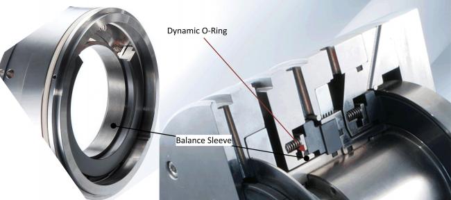
Figure 4. Dynamic secondary O-ring seals: When stretched across the balance sleeve, the O-ring creates additional resistance for stationary face axial movement.
Explosive Decompression
Pressures of more than 800 psi are another concern when dealing with O-rings. The compressor must be depressurized at a rate of no more than 300 psi per minute or explosive decompression can occur, damaging the O-ring and resulting in a dry gas seal failure. O-rings also have limits for temperature and chemical resistance. To resolve these issues, use polymer gaskets.
Reliable Seal Design
Silicon carbide and crystalline diamond coatings allow for conformity between the stationary face and the rotating seat. It will manage any contact between the face and seat or particles that pass between them. The efficient, three-dimensional groove design will compress the gas, forcing it into the seal gap and allowing debris to easily flow with the gas stream.
A dynamic secondary seal design, using a Tungsten Carbide balance sleeve along with polymer static seals, will provide unlimited shelf life. This dynamic secondary seal design moves with little restriction, preventing seal hang-up. It also will handle changing pressures and temperatures without extruding the gasket. The polymer static seals will manage any issue with depressurization rates, wide temperature capabilities and chemical resistance. Having all the correct features designed into the dry gas seal results in high reliable operation.
The next article, in the April 2012 issue, will discuss how to identify the type of separation and process seals required for a dry gas seal cartridge.
Pumps & Systems, March 2012
