

Understanding the interaction between pump curves and system curves is critical to ensuring proper system operation. A pump vs. system curve provides information about where a pump will operate on its curve. There are other benefits a pump vs. system curve can provide, such as improving the operating proximity to the pump’s best efficiency point (BEP), staying within preferred and allowable operating regions of the BEP during abnormal operating circumstances, the impact of throttling valves or control valves on system behavior, etc. The interaction of pump vs. system curves also provides information about when operating multiple pumps in series or in parallel configurations will provide benefits.
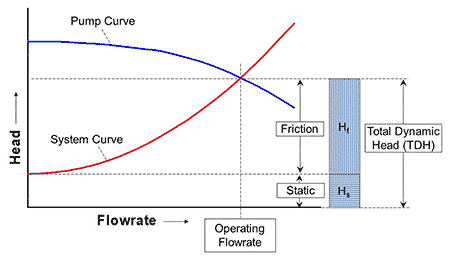
Force mains are a critical application in the water industry. Adding multiple pumps in parallel can help increase flow capacity, but how much additional benefit do the multiple pumps provide? To help answer this question, it is first important to understand what components make up a pump vs. system curve. Image 1 provides an example of a pump vs. system curve.
The pump curve is provided by the manufacturer, and this dictates the pumps’ performance. Pump curves represent how much head (or pressure) the pump can generate at a given flow rate. The system curve represents the resistance through the system at a given flow. When the pump curve and the system curve are superimposed on each other, the point at which they interact is the operating point. This is the flow rate at which the pump will run. At this point, the system curve represents the requirement in pressure to overcome the system resistance, while the pump curve represents the head (or pressure) it can provide to overcome the resistance at the operating flow rate.
The shifting of the system curve about the Y-axis represents the static head of the system. The static head is the difference in the liquid surface elevations from the supply to the discharge locations. If the supply and discharge locations are pressurized, such as with pressurized tanks, then the static head component will include the differences in pressurization as well.
To generate any flow at all, the pump must be able to provide at least enough increased head (or pressure) to overcome the difference in elevation. The static head is typically a fixed value that does not vary with the flow rate in the piping system. However, it can shift with changes in liquid elevations of the supply or discharge locations or if there are changes in pressurization of the supply or discharge locations. This will shift the static head for the system curve accordingly. Note that the concept of static head becomes more complicated and may not be as meaningful if there are multiple branching flow paths in the system that discharge at different elevations.
The frictional head is the resistance in the system that is represented by the system curve, which is a function of the flow rate. The frictional resistance of the system follows a quadratic relationship where at higher flow rates, the resistance significantly increases. The quadratic relationship of the system curve will change as the friction of the system changes. There are many factors that will impact the steepness of the frictional head component of the system curve, and for the sake of simplicity, this article will not focus on those aspects.
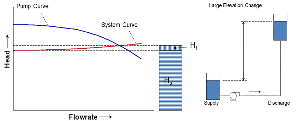
The biggest takeaway is a system curve is made up of two components—the static head and the frictional head—which, when added together, are the total dynamic head that a pump must be able to provide at a given flow rate. Many systems will fall into the categories of being either “static dominated” or “friction dominated.” A static dominated system is one that typically has large elevation differences a pump must overcome. These systems will have a much flatter shape to the system curve but will have a significant static head that dominates the system’s overall resistance. There still is a variability of frictional resistance to static dominated systems, but this impact is small in comparison to the system flow resistance due to elevation changes. Image 2 represents a static dominated system.
As the elevation changes in the system cause the static head to shift up and down, the frictional resistance changes in the system cause the steepness of the system curve to change. Consider a case where a valve is fully open in a system. The valve represents a form of frictional resistance.
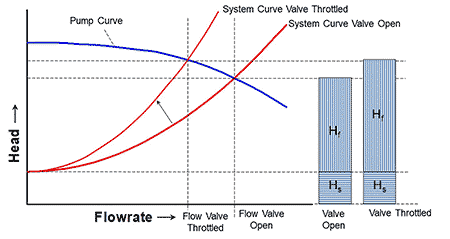
If this valve is closed by a certain amount, it will increase the frictional resistance in the system. The system curve will still intersect with the pump curve and the added resistance will lead to a decrease in flow, as well as the additional amount of pressure needed from the pump. Image 3 represents a friction dominated system.
Understanding the fundamental shapes of the system curves for static or friction dominated systems will help provide guidance as to when adding more pumps into a parallel configuration will increase flow. Very long pipelines will typically add pumps in series at different locations along the flow path to continually increase the system pressure as needed. This may not be needed as often in force mains, because force mains are usually not incredibly long pipelines but are more on the order of several hundred to thousands of feet. Therefore, pumps in series may not be needed as often.
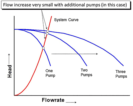
However, operating multiple pumps in parallel configurations for force mains is a lot more common. This will help generate additional flow to the system, but the addition of more and more pumps will quickly lead to a diminishing return. This is where the shape of a system curve matters. When pumps are operating in parallel configurations, the flow rate is additive for a given pump total dynamic head (TDH). Steep system curves represent friction dominated systems, and the addition of each pump will generate less and less flow. Image 4 demonstrates how, for this friction dominated system, even adding two or three pumps in parallel does not generate much more additional flow.
Overall, force main piping systems will typically have contributions of both static head and frictional head that need to be overcome, and operating multiple pumps in parallel can certainly help obtain additional flow. This works well for initial designs; however, if there is a desire to increase flow capacity down the road, simply turning to the option of adding more pumps may not be helpful and might require additional design, which can potentially include changes to the piping itself.