


This is the first in a three-part series. Read part 2 here.
So, you need to build a piping system to move 500 gallons of water per minute from point A to point B? No problem, I will call my buddies over at ACME Pipe4U and see what’s on sale. What could possibly go wrong? Please read on.
Reading this column will not make you a piping system expert, and for the record, I am not an expert either. However, I do know a bad pipe system design when I see it.
In this column, I hope to shine some light on the most common pipe system problems that directly affect the pump. You can inspect, evaluate and compare your system to these real-world issues. My comments are focused on horizontal centrifugal pumps in nonslurry applications that are used for pumping nonviscous Newtonian fluids.
First Things First
What’s so important about the piping system? It is the characteristics of the piping system that dictate how and where the pump operates on its performance curve. Where the pump operates on its curve will dictate its life span, reliability and overall total operating cost. The pump will inevitably and erroneously be blamed for all of the problems that occur, but in 98% of the cases, it is not the pump’s fault. Technically, you should design the piping system first and then find the right pump to match. The pump and the associated system, like a good marriage, must be matched to each other. Otherwise, it will be a continuous stream of drama-filled issues followed by unnecessary expenses and finally a divorce.
Pipe Size
If you need to pump water a distance of 1,000 feet at a flow rate of 500 gallons per minute (gpm) from point A to point B with no elevation change, what size should the pipe be? Your friends over at the bargain pipe store have 2.5-inch pipe on sale, so you decide to buy what you need. The problem is that the friction loss for a 2.5-inch pipe at the flow rate of 500 gpm is about 163 feet (friction loss) per every 100 linear equivalent feet of piping (remember, you need to pump the water a distance of 1,000 feet). The money you initially saved on the bargain pipe will cost you dearly in both the initial pump cost (likely a two-stage pump will be required), but more importantly the operating costs over time. It takes horsepower (hp) to operate the pump and that translates directly into kilowatt hours (kWh), and that looks like a lot of money when the electric bill comes due. If you had decided on 6-inch pipe in lieu of the 2.5-inch, you would have initially paid more for the pipe, but your operating hp would drop significantly from an estimated 280 brake horsepower (BHP) down to less than 10 BHP.
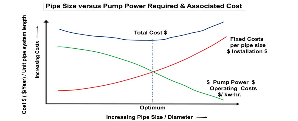
In this example, I am approximating what appears to be an extreme and seemingly ridiculous situation, yet I have witnessed similar real-world examples. The lesson to be learned is that there is an optimum pipe size for each system where the total system cost is balanced between the operating costs over time as compared to the initial cost for the specific pipe size. Perhaps the 6-inch pipe I previously mentioned would be too expensive and the 4-inch pipe would be a better choice?
The 5-inch pipe may be better from a head loss aspect, but it is an odd size and may not be in stock or may be even more expensive than the 6-inch pipe. You and/or a pipe system professional would need to perform the calculations to determine the most correct answer.
As a general rule for nonslurry applications on the discharge side of the pump, it is best to keep the liquid velocity below 10 feet per second (3 meters per second) and anything over 15 feet per second (4.5 meters per second) should
be questioned.
Note: Frequently the velocity measured directly at the pump discharge nozzle will be much higher than 10 to 15 feet per second, and it is expected that larger pipe will be incorporated downstream of the nozzle to yield lower velocities and friction losses.
The calculations to determine the optimum pipe size and the system curve can range from simple to very complex, and if you are not experienced or familiar with Darcy-Weisbach, Hazen-Williams and Bernoulli’s equations or the estimation/calculation of Reynolds’ numbers, you should contract a professional for assistance.
The general idea is that the head loss (pipe friction) is roughly proportional to the square of the flow rate.
- A few estimating rules of thumb:
- Doubling the diameter of the pipe will increase the capacity by four times.
- The friction losses vary as the square of the capacity ratio.
- Doubling the flow in a given pipe size will increase the head loss by a factor of four.
- The friction loss is inversely proportional to the pipe diameter ratio raised to the fifth power.
- The capacity of a pipe varies as the diameter ratio raised to the 2.5 power.
To be more specific, you will need to use the Darcy-Weisbach approach; the formula is shown in Equation 1.
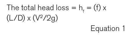
Where f is a variable friction factor and depends on the inside pipe surface roughness. The f is derived from the CF Colebrook equations and the Moody diagram. L is the length of the pipe. D is the diameter of the pipe. V is the average velocity of the liquid in the pipe. And g is the acceleration due to gravity. The Darcy friction factor f has no units. All units are either feet or meters, except note that the acceleration of gravity is 9.81 meters per second squared (m/s2) for the SI system and 32.2 feet per second squared (ft/sec2) for the USC system. You also need to calculate and compensate for the age of the pipe system. The friction factor will change with age, and especially in raw water intake systems you also need to take marine growth and fouling into consideration.
Note that it is also feasible to use the Hazen-Williams equation in your approach (not shown) for pipes sizes under 36 inches and for ambient temperature water only.
Finally, note that selecting the pipe size based solely on the pump flange sizes is usually not a good idea. Again, I point out that the system should be designed first before selecting the pump. In most cases, the optimum pipe system design and best practices will dictate a different and larger pipe size. The suction line on a self-primer pump would be an exception.