


Major pharmaceutical manufacturers use chillers to maintain the temperature in the laboratories and production facilities throughout their campuses. The loss of the ability to maintain optimal temperatures within these facilities, especially laboratories, can mean the difference between a successful production run or millions in lost revenue, not to mention the impact on new pharmaceutical discoveries, or equipment failures and delays.
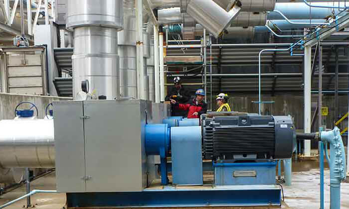 Image 1. The subject pumps are driven by 200-horsepower induction motors. (Images courtesy of ProPump Services)
An aftermarket services provider was called in to such a facility to assess a series of five pumps. The subject pumps, which were tagged Nos. 14 through 18, are driven by a 200-horsepower (hp) induction motors (Image 1). They are operated individually or in parallel based on chiller requirements. Pumps Nos. 15 and 18 were tested during the assessment and site personnel reported elevated vibration amplitudes, cavitation noise, impeller damage, and short bearing and seal life.
Suction Piping
The suction inlet source is a common channel between two cooling towers. The suction inlet to each pump is a 20-inch pipe with a scalloped opening at the 6 o’clock position running perpendicular across the channel (Image 2).
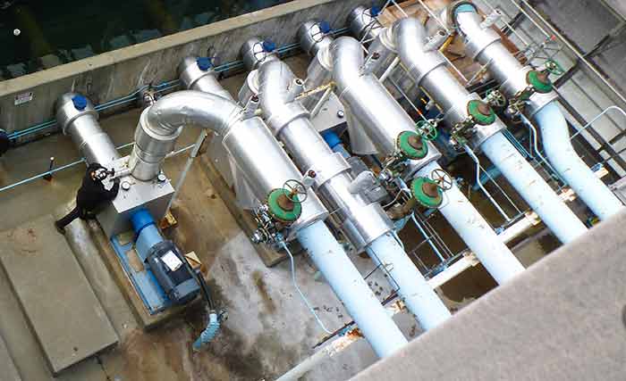 Image 2. Pump No. 15 is the first pump to the right, and No. 18 is the last pump to the left. The suction inlet to each pump is a 20-inch pipe with a scalloped opening running perpendicular across the channel. (Images courtesy of ProPump Services)
It was suspected that the existing suction inlet design was the root cause of the damaging cavitation occurring within the pumps.
Investigation
The investigation began with determining the existing hydraulic and mechanical condition of the subject pumps. The pumps were tested individually, then in parallel with each other. Pump design reviews, review of maintenance and operational historical records, and measurements of each pump and motor operating parameters included:
- discharge flow (gallons per minute)
- suction and discharge pressures (pounds per square inch gauge)
- temperatures (degrees Fahrenheit)
- pump speed (rate per minute)
- motor current and voltage (volts of alternating current, amps)
- vibration signatures
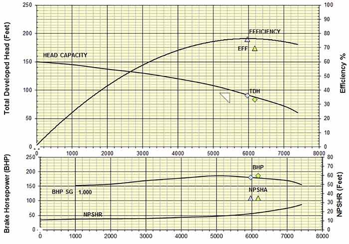 Image 3. Both pumps were operating at or near expected levels and with sufficient NPSHa.
As indicated in Image 3, both pumps were operating at or near expected levels and with sufficient net positive suction head available (NPSHa).
The unfiltered velocity amplitudes from both pumps were at or below 0.16 inches per second (ips)-peak, which was measured on pump No. 18. However, a review of the associated time waveforms and spectra (Image 4) provides insight to the composition of the vibratory energies.
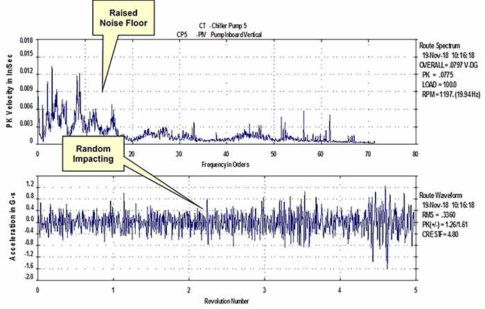 Image 4. The spectrum presented reveals a significantly raised noise floor and random impacting in the time waveform, both indicative of hydraulic instability.
The spectrum presented in Image 4 reveals a significantly raised noise floor and random impacting in the time waveform, with both indicative of hydraulic instability.
Technical Discussion of NPSHa, NPSHr & Submergence
NPSHa is defined as the total suction head in feet of liquid (absolute at the pump centerline) less the vapor pressure. Net positive suction head required (NPSHr) is determined by the pump manufacturer and is a function of several factors, including impeller eye design, flow, shaft speed, etc. For all operating conditions, the NPSHa must exceed the NPSHr.
Submergence is the minimum intake or suction depth required to prevent surface and subsurface vortices, excessive flow re-whirl and more.
For these installations the NPSHa to NPSHr was deemed adequate and within the acceptable margin of 10 to 35 percent. However, submergence is inadequate and surface vortexing was observed at the inlet to pump No. 18, as shown in Image 5. Vortexing allows air ingestion into the impeller eye and resultant cavitation.
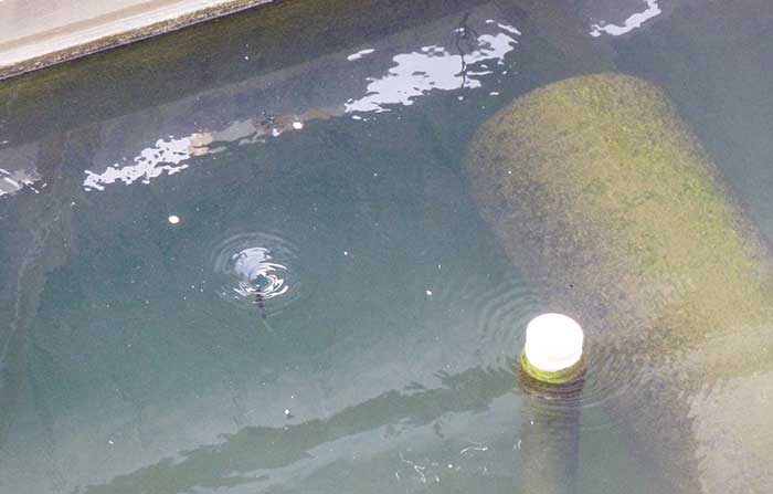 Image 5. Submergence is inadequate and surface vortexing was observed at the inlet to pump No. 18.
Cavitation or Suction Recirculation
Cavitation occurs when the absolute pressure of the liquid falls below its vapor pressure within the impeller or casing. The cavitation bubbles are swept through the impeller (or casing) to a regime of higher pressure where the bubbles implode rapidly. The energy release manifests as noise (crackling or popping), and damage to the pump components as the hydraulic impacts are sufficient to fatigue the impacted material. Over time the released hydraulic energies can cause damage to seals, impeller, casing, shaft and bearings, to the point of compromising their integrity and decreasing the mean time between failure (MTBF) rates.
Insufficient NPSHa can result in increased suction recirculation, inducing cavitation reversing secondary flows, or eddy currents formed in the eye of the impeller, further exacerbating the NPSHa problem. Flow separation can occur when the incidence angle or the difference between the angle of the flow and pump vane inlet angle exceeds the critical value for a given impeller design.
Suction specific speed (NSS) is an index of hydraulic design describing the suction capabilities and impeller characteristics. Impeller designs with an NSS above approximately 8,500 are particularly sensitive to operation at flow rates above or below the best efficiency point (BEP) and susceptible to suction recirculation. This can occur especially in cold water (the cavitation energy released in the water below 60 F is significantly greater than hot water cavitation). In this case, the subject pumps’ NSS was 10,500 and had an increased propensity for suction recirculation damage during off BEP operation.
Conclusions
Hydraulically, both pumps were operated at or near expected levels. The vibration amplitudes measured from both pumps were at acceptable limits for this pump type. However, spectra and time waveforms revealed significant hydraulic anomalies.
The observed creation of surface vortices at the inlet to pump No. 18 (Image 5) while operating in parallel with pump No. 15 suggested the submergence at No. 18 was less than that of No. 15 due to its location in the middle of the channel. It was reasonable to assume that with more pumps operating in parallel with No. 18 that vortex creation, both surface and subsurface, occurs with greater frequency, thus, becoming more problematic. The truncated MTBF rates of the bearings and seals are attributable to suction flow instabilities and cavitation resulting in the reported significantly elevated vibration amplitudes.
Recommendations
Taking all of this into account, the aftermarket service provider recommended conducting a hydraulic study of the inlet to investigate optimizing the inlet basin and suction flow into the pumps by increasing the submergence within the confines of the existing basin.
References
“Centrifugal and Axial Flow Pumps, Theory, Design, and Application 2nd Ed,” Krieger Publishing Company, Malabar, Florida 1993 - A.J. Stepanoff, Ph.D., chapter 16, section 16.2 (a) submergence pages 357-358.
“Pump Handbook 2nd Ed”- I.J. Karassik, W.C. Krutzsch, W.H. Fraser, and J.P. Messina, section 10.1, recirculating systems-cooling towers, pages 10.8- 10.9, multiple pumps, pages 10.9-10.12.