


In my last column (Pumps & Systems, October 2014), I explained that a capacitor’s current is totally out of phase with that of a motor’s magnetizing current. This allows the capacitor to store current when the magnetic field collapses and return it to the stator when the magnetic field is building. The net effect is a much improved motor power factor (PF). Two methods can be used to improve PF with capacitors.
Static correction involves using capacitors to correct a single load. They can be installed at several locations. Static correction can be the most effective method, but it can also be the most expensive. Bulk correction uses a bank of capacitors that improve PF for different parts of a facility. These capacitors can be switched in and out of the circuit depending on the monitored PF.
Capacitor Location Options
The location of a static capacitor or capacitor bank installation has a major effect on where PF is improved. For example, capacitors provide only upstream correction and relieve all upstream wiring and components of the current required to create a magnetic field in an inductive device. All wiring and electrical components that are downstream of the installation still must be sized to carry both the load and magnetizing currents.
Figure 1 is a simplified sketch of a plant’s electrical system that illustrates the effect of capacitor location. On the far left is the utility entrance and its kilowatt-hour (kWh) meter. Next is a transformer that provides the plant’s supply voltage. To the right of the transformer is a motor control center (MCC) that is used to operate the plant’s alternating-current (AC), motor-driven equipment.
On the far right is a single AC motor. The red capacitor symbols (1 through 4) show the possible locations for capacitor installation. In a real plant, this diagram would be much more complex. It could include multiple transformers and branch circuits feeding various portions of the plant, several MCCs and dozens of AC motors.
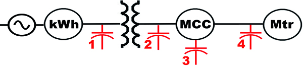 Figure 1. Sample sketch of a plant electrical system (Graphic courtesy of the author)
Location 1
The plant could install a capacitor bank at Location 1 if the utility is charging a penalty. This would relieve the utility of supplying the magnetizing current to the plant and make it available for sale to other customers. Typically, the bank would be operated by a PF controller that would switch individual capacitors on and off based on the measured PF of the entire plant. This would eliminate the penalty but will not change the PF downstream of the bank.
Location 2
The capacitor bank could also be installed at Location 2, which is the secondary side of the plant’s transformer. This location will still relieve the utility and increase the transformer’s capacity.
For example, an 800-kilowatt (kW) transformer can provide 640 kW of usable power at a PF of 80. If PF is increased to 95, it could provide 760 kW, about 19 percent more. This bank would be operated with a controller that switches capacitors on and off as needed.
Location 3
The capacitor bank from Location 2 could also be installed at Location 3, just before the MCC. This would reduce the load on the wiring from the transformer to the MCC.
Individual (static) capacitors can also be installed at the input or output of each motor controller at the MCC. Either location will eliminate the need for a capacitor bank and its associated controls while reducing the load from the transformer to the MCC.
If the capacitors are installed on the input side of the controller, a separate contactor is often required to automatically remove them from the circuit when the motor is off. If the capacitors are installed on the output side of the controller, several control panel components can potentially be downsized on new installations.
Location 4
Static installation at the motor—Location 4—is the most efficient location. All upstream wiring and electrical components are relieved of the magnetizing current portion of the load required by that motor.
If the installation is for a previously installed motor, it can also be more costly because the panel overload device will usually require replacement.
Never connect a capacitor downstream of a variable frequency drive or solid state soft starter. When installed upstream, the manufacturer should be contacted for the required distance.
Other Concerns
PF changes when the line voltage varies from the nameplate voltage. PF increases by about 3 percent when a 460 volt (V) motor operates at 440 V. When operated at 480 V, PF decreases by about 5 percent. The decrease is nearly directly proportional to the voltage increase.
Lightly loaded motors also decrease PF. At three-fourths load, PF is reduced by about 5 percent. At one-half load, it is reduced by as much as 12 percent.
Induction motors are not the only source of low PF in the industrial sector. Fluorescent and mercury vapor lighting systems exhibit a very low PF, in the range of 0.4 to 0.6.
Arc and resistance welding machines also have a PF in the same range.
On average, a typical industrial plant will have an uncorrected PF of 0.75 to 0.8. Increasing the PF to 0.95 can eliminate utility penalties and increase the efficiency of a plant’s electrical grid.
Other sectors also contribute to low PF. Large commercial facilities, such as hotels and malls, can have significant inductive loads.
In the residential sector, homes have many small motors that power washers, dryers, refrigerators, air conditioners, heating systems and other devices. Although most are fractional horsepower, they typically have a very low PF (0.6 to 0.7).
When all the small motors run together, they may produce between 1 and 2 horsepower.
Multiply that by several thousand homes, and PF becomes a significant problem for the utility. That is why utilities have their own PF correction facilities spread throughout their distribution systems.
Resources
Several resources can provide more information on PF correction.
The first two cover larger installations, and the third covers correction for a single motor. They will also help you determine if PF correction is worth the investment.
- Power Factor in Electrical Energy Management pdhonline.org/courses/e144/e144content.pdf
- Power Factor Correction: A Guide for the Plant Engineer eaton.com/ecm/groups/public/@pub/@electrical/documents/content/sa02607001e.pdf
- The Cowern Papers pumped101.com/index.html#cowern