In the fifth century BCE, the famous Chinese Tao philosopher Lao Tzu stated, “When the student is ready, the teacher will appear.” There are several sources that will argue the veracity of Tzu ever making these statements (no cellphones in 550 BCE), while some say that his teachings are romanticized.
Regardless of its origin, I am highlighting this proverb because over the last 11 years of writing this column, I have all too often discussed the reasons why centrifugal pumps on a suction lift system may fail to properly perform. Clue: It is rarely the pumps’ fault. Yet, in recent months, I have been asked to help in solving operational problems with pumps in a suction lift service. Perhaps the teacher had not yet appeared for these folks. Consequently, this column is intended as a refresher on the basics of dealing with centrifugal pumps in a suction lift system.
1. Suction Lift
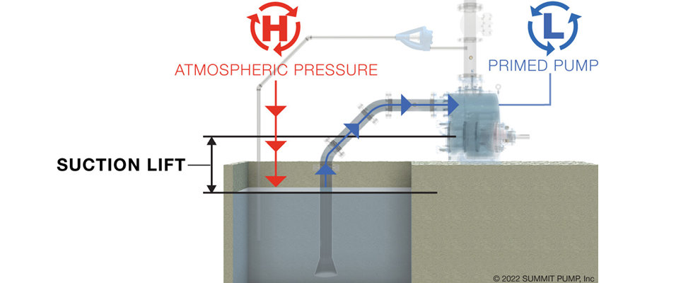
When the pump is physically located above the level of the liquid to be pumped, it is considered a suction lift. “Lift” is the vertical distance from the centerline of the pump suction flange to the lowest expected level of the liquid. Note the pump centerline/suction flange and the impeller centerline may be different, so when in doubt, use the impeller datum point. The measured level of the liquid surface should be the lowest level expected (worst case).
There are two different suction lift definitions/conditions, one of which is static and the other of which is dynamic. Static lift is simply the vertical measurement with the pump system not operating. Dynamic lift is the previously mentioned static lift plus friction and other minor factors that occur when the system is operating.
I blame the terminology for the misunderstandings on this subject. The term “suction lift” invokes a line of thinking in which the pump is pulling a suction on the liquid and will subsequently suck, pull or lift the liquid into the pump. This is a very misleading visualization. The pump cannot pull, lift or suck liquid because liquids do not possess or exhibit tensile strength. (For the technical folks, I acquiesce that the impeller does create a small differential pressure adjacent to the eye of the impeller.)
What is really happening is the liquid is being pushed into the suction pipe by some external force. Normally in the case of a suction lift, that force is atmospheric pressure. In the context of this column, I am assuming the system supply source is open to atmospheric pressure.
In a perfect world, a proper pump can theoretically lift 34 feet when operating at sea level with water that is 68 F or cooler. The real world is far from perfect, and the pump system is never at sea level. Consequently, most experts will tell you that 25 feet is the maximum lift for ambient temperature water. I’m sure some readers will have a marginal example where the lift is greater than 25 feet. However, I recommend using 25 feet as the prudent boundary, and you should proceed cautiously from there with a safety factor. Friction, vapor pressure, viscosity and the actual static lift height will be your enemy in this battle of physics.
2. Net Positive Suction Head
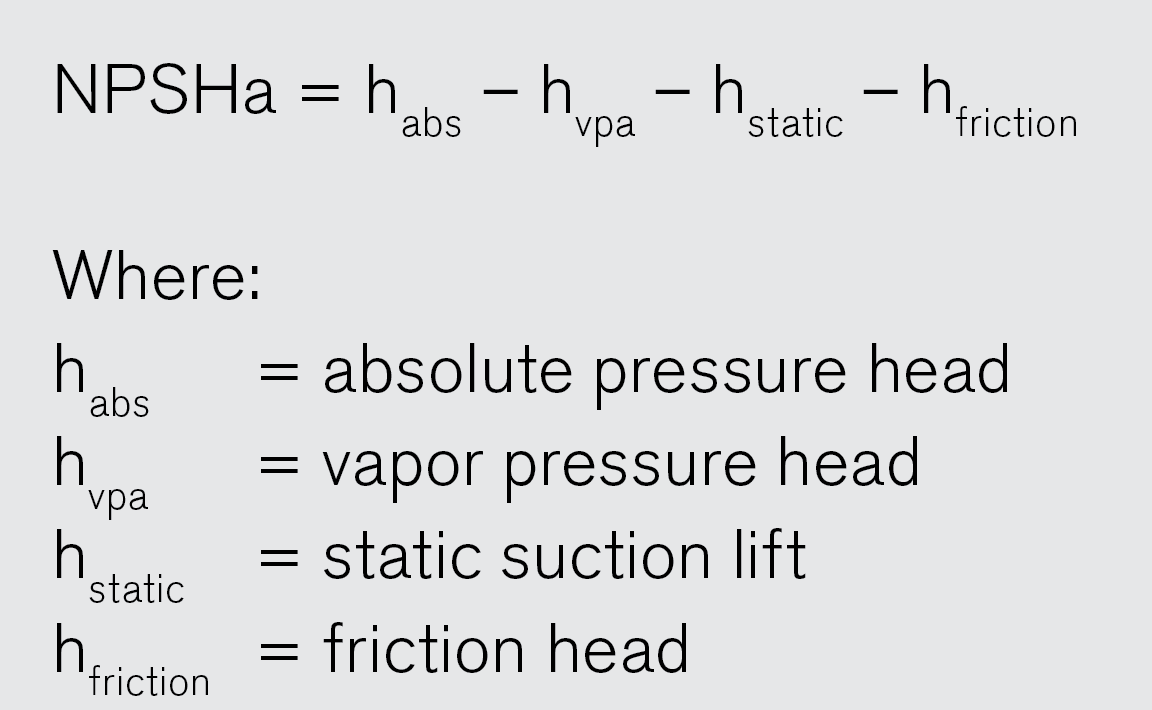
The suction side of the system will possess a certain amount of net positive suction head available (NPSHa), and the pump will demand a certain amount of net positive suction head required (NPSHr). The difference between the two is referred to as the margin or the ratio. You must have more net positive suction head (NPSH) available than required—that is, you always need a positive margin.
For more details on calculating or understanding NPSH, please see my column from October 2021, “Rethinking the NPSH Matrix” and my 6-part series on NPSH from July to December 2018.
3. Specific Gravity
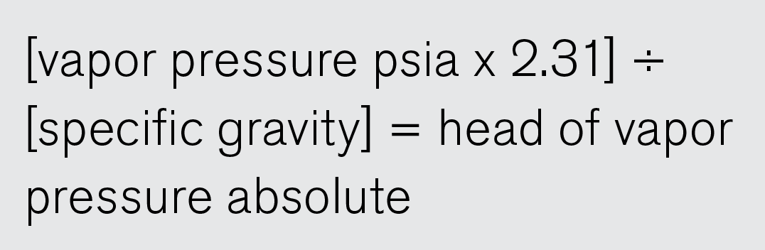
This factor may not be readily apparent to the casual observer. Consider the equation for the calculation of absolute head based on atmospheric pressure at sea level:
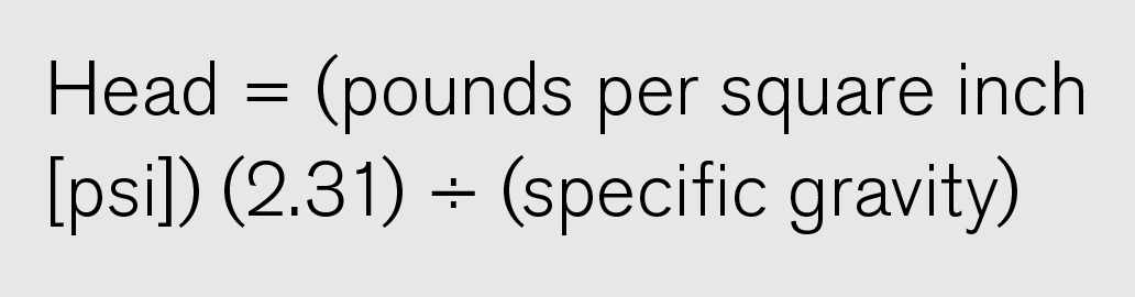
Note the specific gravity is in the denominator and so it has an indirect effect. The equation for calculating the head of ambient temperature water is as follows:
As a safety factor, I normally violate the traditional rules of mathematics and round down to 33 feet absolute for the atmospheric pressure at sea level. As an argumentative example, assume your liquid has a specific gravity of 1.3. Subsequently, the resultant head will be 26 feet, a reduction of 8 feet.
4. Elevation Above Sea Level
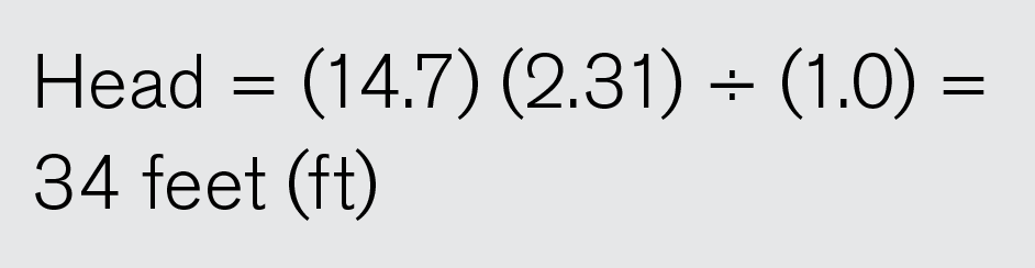
As mentioned previously, 34 feet is the theoretical maximum suction lift when pumping 68 F water at sea level in an open system. It seems like all basic pump tutorials are based on examples at sea level where the absolute atmospheric pressure is 14.7 pounds per square inch absolute (psia), which converts to 34 feet (figures are rounded and barometric pressure changes are ignored). In real life, the pump will rarely be at sea level. At 3,000 feet elevation above sea level (EASL or ASL), the absolute head drops to 30.5 feet, and at 5,000 feet ASL, it decreases even more to 28.2 feet. You may be thinking that a loss of 5 or 6 feet doesn’t mean much, but in the scary world of NPSH margins, one foot can make the difference between success and failure.
In addition, it is important to remember that engines and motors are also derated as elevation increases.
5. Submergence
Submergence is the vertical distance from the surface of the liquid to the pump suction intake. Critical submergence is the required vertical distance to prevent vortexing (whirlpool), which leads to air entrainment. Vortexing is a function of the liquid velocity entering the suction line, the liquid properties and the depth of submergence (vertical distance). Air entrainment, even at the low amount of 2% to 4%, will handicap the pump performance. Critical submergence should be calculated to avoid this issue. Please see my column on submergence in the April 2016 edition and air entrainment in the December 2017 edition.
6. Vapor Pressure (Temperature)
The vapor pressure of a liquid is the pressure necessary to keep the liquid from vaporizing (boiling) at a given temperature. Vapor pressure for liquids increases in a nonlinear fashion as the temperature increases. As I have pointed out in earlier columns, in the pumping world, vapor pressure is never your friend. For liquid (water) temperatures below 70 F, the negative contribution is marginal at approximately 1 foot (0.84 feet for water).
Vapor pressure in the United States customary units of measurement (US-C system) is typically expressed in units of psia, so when you look it up in a reference chart, you will need to convert the absolute pressure to absolute head.
Always be sure to use the specific gravity that correlates with the liquid temperature. There are various equations you can use to calculate vapor pressure, but I find it easier to simply look it up in a trusted reference book or website (one less opportunity to make a math error).
I become concerned when the liquid temperature approaches 100 F and the vapor pressure is about 2.2 feet absolute. Remember that it is a factor working against you in the NPSHa equation. By the time the temperature reaches 140 F, the vapor pressure is approaching 7 feet, and when combined with friction factors and the head of static lift, it will usually negate the possibility of a successful lift. For a more detailed explanation of vapor pressure, please refer to my column in the April 2018 issue.
7. Viscosity
Viscosity is the kryptonite of centrifugal pumps. The viscosity of a liquid is the measure of its resistance to flow, and it varies inversely with temperature. As temperature goes up, viscosity goes down. Viscosity will seriously handicap the flow rate, head and efficiency of the pump. My column from November 2017 explains this in detail.
8. Suction System Integrity
Many people are surprised to learn that during pump operation, the suction side of a lift system is typically at a pressure below atmospheric (partial vacuum). Consequently, the integrity issue is not liquid leaking out of the system but air leaking in. All connections and flanges must be airtight, which is a higher degree of permeability than liquid tight. An airtight system is inherently liquid tight, but a system designed only to be liquid tight may not be airtight.
9. Friction
Like vapor pressure, friction is also your nemesis. All components in the piping system will present a certain amount of friction, including the piping itself. Elbows, valves, tees, strainers, heat exchangers, reducers, nozzles and even changes in pipe size will all present a summary friction factor. The older the system, the more the friction will increase. For a detailed description of the system friction (resistance) curve, please refer to part 2 of my column from February 2023 titled, “The System Is the Boss.”
10. Pump Health
Pump health is the pump mechanical operating condition. This relates to proper clearances and settings, balance, speed, pipe strain and alignment. Refer to the manufacturer for guidance.
9 Tips for Successful Operation
1. Always calculate for both NPSH margin and critical submergence. You may have sufficient NPSH but inadequate submergence. The antithesis is also true; you may have sufficient submergence but inadequate NPSH. Always calculate for the worst case.
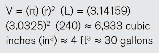
2. Keep the suction line as short as possible. Every increment of piping length presents additional friction, and along with the diameter, it represents an added volume of air and noncondensable gases that must be expelled. Twenty feet (240 inches) of 6-inch schedule 40 pipe is approximately 4 cubic feet (ft3) of volume or about 30 gallons of water.
In flooded pump systems, the suction pipe is purposely one or more sizes larger than the pump suction flange, but a common practice in suction lift applications is to design the suction pipe size the same diameter as the pump suction. This is a normally acceptable design compromise between air volume reduction and increased friction.
3. Design the suction line to rise continuously to the pump to prevent air traps that will block flow. Reduce the major cause of liquid swirling, which is pipe bends. Obviously, you can’t avoid at least one bend, but added bends in the suction pipeline should be avoided. Multiple pipe bends should be in one plane only. Design to keep the liquid velocity ideally below 6 feet per second but no more than 8 feet per second.
4. To preclude or mitigate friction factors, most piping systems for static lift will not have an isolation valve. If a valve must be installed, position the valve so the stem is horizontal to the pipe plane to avoid air pockets.
5. Foot valves (suction check valves) are handy items when they work and will reduce priming time. The real-world issue is knowing or predicting when they fail or become clogged. Foot valves are difficult to replace and add friction, which reduces NPSHa.
6. Question whether you really need a strainer on the suction line. Most pumps will handle a small degree of entrained solids, and most self-primers are specifically designed to handle some solids. Always check with your manufacturer and note most American National Standards Institute (ANSI) pumps are limited in this respect. If you absolutely must have a strainer, at least put differential pressure instrumentation across the unit. I recommend that the total area of the openings in the strainer be at least three or four times the cross-sectional area of the suction line. For a detailed explanation, please refer to my January 2019 column titled, “Best Practices for Strainer Location.”
7. During the priming process, the air in the suction line must have somewhere to go. The pump is not a compressor/blower. Proper installations will allow the air to vent (typically back to the sump). The vent connection must be upstream of both the discharge check and isolation valves.
8. All centrifugal pumps on a suction lift, whether self-priming or primed by an external system, must be initially primed. Calculate the priming time required for your system. This is just a silly rule of thumb, but I recommend that if the pump hasn’t primed in 4 to 5 minutes, you need to shut down and figure out the problem. If the pump’s mechanical seal is cooled/lubricated by the product that is being pumped, it is very possible to flash the liquid in the seal chamber and destroy the faces. Check to see if the pump casing is hot/warm, because if the water in the priming chamber gets too hot, it may also flash to vapor.
9. Look at where you are on the pump curve. The further right on the curve (more flow and NPSHr), the less vertical distance you will be able to lift. Select a pump that is left of the best efficiency point.
To quote one more Chinese proverb of dubious origin (some say it’s meant as a curse), “May you live in interesting times.” I agree that we do, whether you are a student, a teacher or both.
References
- Hydraulic Institute/ANSI Specification 9.8 Hydraulic Intake Design
- The Pump Handbook 4th edition, Paul Cooper & Charles Heald et al.
- Troubleshooting Centrifugal Pump Field Problems, Robert Perez
- Cameron Hydraulic Data, C.C. Heald et al.